Repair Section
2
–
105
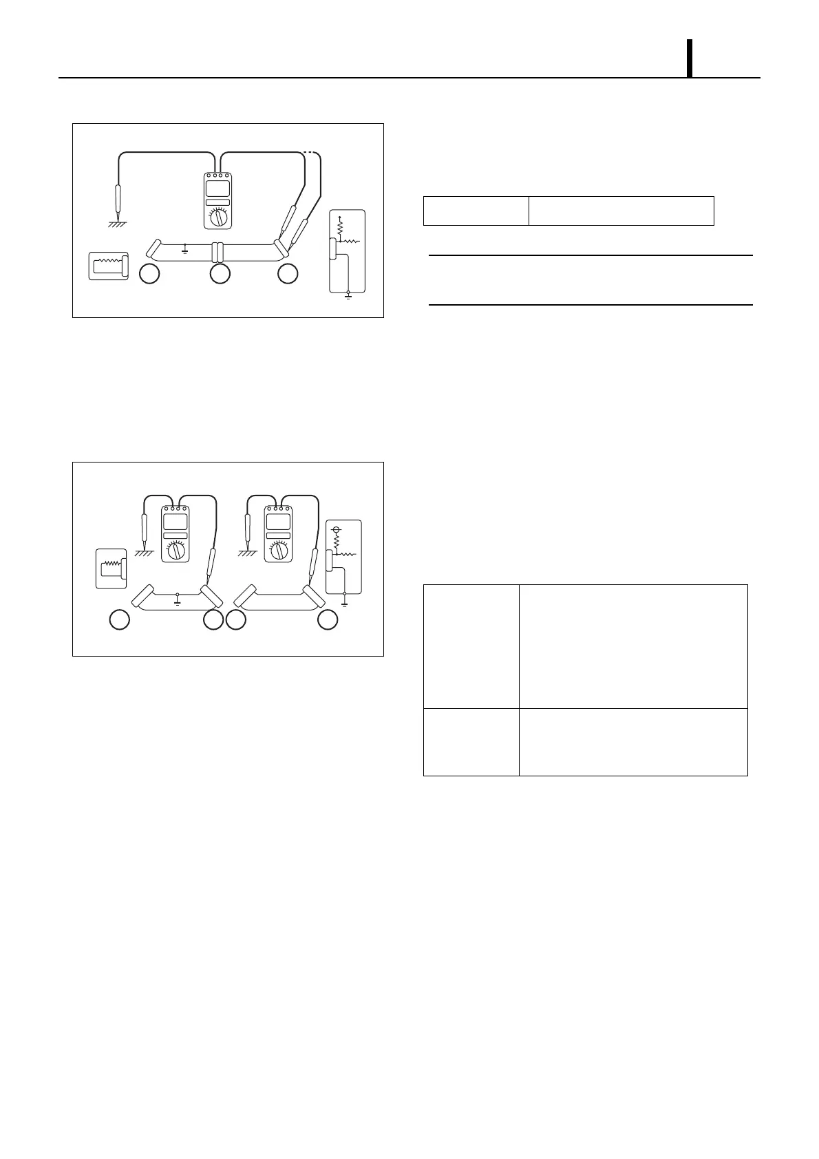
Ground Continuity Check
1) Remove connector "A" and connector "C", and then mea-
sure the resistance respectively between terminals 1 and 2
of connector "A" and ground.
< NOTE >
Measure resistance while gently shaking the wiring har-
ness up and down, and side-to-side.
2) As shown in diagram 6, there is continuity between terminal
1 of connector "A" and the body ground (short circuit). How-
ever, there is no continuity between terminal 2 of connector
"A" and the body ground. Therefore, there is a short circuit
between terminal 1 of connector "A" and terminal 1 of con-
nector "C".
3) Remove connector "B" and measure the resistance be-
tween terminal 1 of connector "A" and the body ground, and
between terminal 1 of connector "B2" and the body ground.
4) The faulty circuit and measurement results are shown be-
low.
Q002332E
Diagram 6
Sensor
Engine
ECU
1
22
11
2
ABC
Standard Value 1Ω or less
Q002333E
Diagram 7
Sensor
Engine
ECU
1
2
1
2
1
2
1
2
ACB2B1
Measurement
Results
• There is no continuity between termi-
nal 1 of connector "A" and the body
ground.
• There is continuity between terminal
1 of connector "B2" and the body
ground.
Faulty Item There is a short circuit between terminal
1 of connector "B2" and terminal 1 of
connector "C".