Operation Section
1
–
84
3) Checking the Freeze Frame Data: If the symptom that out-
puts a DTC cannot be duplicated, check the freeze frame
data.
4) Erasing DTCs from memory: Operate in accordance with
the instructions shown on the screen to display the "DTC
check" screen. Select "Erase DTCs" to erase the DTCs.
< NOTE >
If it is not possible to erase the DTC, turn the ignition
switch OFF, and repeat the process.
5) Wiring Harness and Connector Open Circuit Check
< NOTE >
If the DTC output during a diagnostic inspection (in the
check mode) has identified the system with a malfunction,
use the method indicated below to narrow down the area
of the malfunction.
• Erasing DTCs from memory: After reading the DTCs in check mode, erase the DTCs from memory.
• Starting the Engine: Select the check mode and start the engine.
• Malfunctioning system check 1: While the engine is running at idle, shake the wiring harness and connectors of the
system that output the malfunction during the diagnosis (check mode) inspection.
• Malfunctioning system check 2: If the MIL (Malfunction Indicator Light) illuminates when the wiring harness and con-
nectors are shaken, there is a poor contact in the wiring harness or connectors in that area.
8.3 Diagnosis Inspection Using The MIL (Malfunction Indicator Light)
z Before reading a DTC, turn the ignition switch ON to make sure the MIL (Malfunction Indicator Light) illuminates.
z Inspections in the check mode cannot be performed.
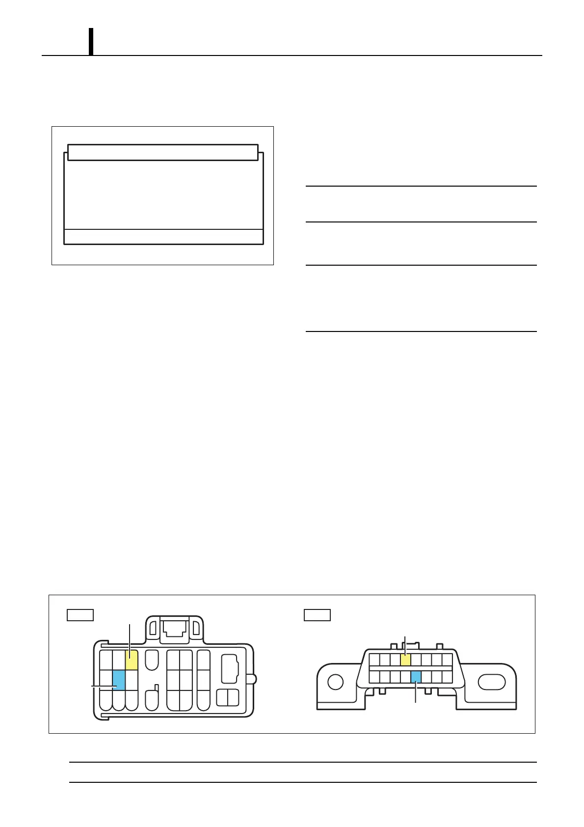
(1) Reading DTCs
Short circuiting the connector
• Using the STT, short circuit between DLC1 terminals 8 (TE1) and 3 (E1) or between DLC3 terminals 13 (TC) and 4
(CG).
< CAUTION >
Never connect the wrong terminals of the connectors as this will lead to a malfunction.
Q000916E
This will erase the DTC and freeze frame data.
Do you wish to proceed?
DTC (ECD Erasure)
NG : - OK : +
4
TE1
E1
TC
CG
123 56
18
789 1011
20
12 13 14
15 16 17 21
22 23
19
16 15 14 13 12 11 10
9
87654321
DLC1
DLC3
Q000917E