Operation Section
1
–
26
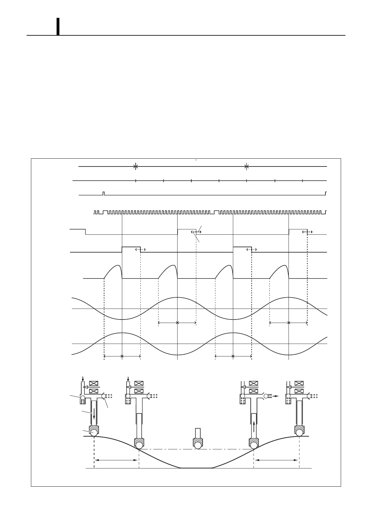
Fuel Discharge Quantity Control
• The diagram below shows that the suction starting timing (SCV (Suction Control Valve) ON) is constant (determined
by the pump speed) due to the crankshaft position sensor signal. For this reason, the fuel suction quantity is controlled
by changing the suction ending timing (SCV OFF). Hence, the suction quantity decreases when the SCV is turned
OFF early and the quantity increases when the SCV is turned OFF late.
• During the intake stroke, the plunger receives the fuel feed pressure and descends along the cam surface. When the
SCV turns OFF (suction end), the feed pressure on the plunger ends and the descent stops. Since the suction quantity
varies, when suction ends (except for maximum suction) the roller separates from the cam surface.
• When the drive shaft rotates and the cam peak rises and the roller comes in contact with the cam surface again, the
plunger is pressed by the cam and starts pumping. Since the suction quantity = the discharge quantity, the discharge
quantity is controlled by the timing with which the SCV is switched OFF (suction quantity).
0 2 4 6 8 101214 16 0 2 4 6 8 101214 0 2 4 6 8 101214 16 0 2 4 6 8 101214
Suction Suction
Suction Suction
Decreased Suction
Quantity
Increased Suction
Quantity
ON
OFF
SCV 1
SCV 2
Suction Pumping
Start of Suction End of Suction Start of Pumping End of Pumping
360 CR
TDC #1
TDC #3 TDC #4
TDC #2
Cylinder Recognition
Sensor Signal
Crankshaft Position
Sensor Signal
ON
OFF
Crankshaft
Angle
Compression
Top Dead Center
Fuel
ON
Plunger
Roller
OFF
Fuel
OFF
Fuel
OFF
Delivery Valve
Discharge
Horizontal
Cam Lift
Vertical
Cam Lift
Check Valve
SCV
Pumping
Suction
Pumping
Suction
Pumping
Suction
Pumping
Suction
Delivery Valve
Q000833E