Operation Section
1
–
63
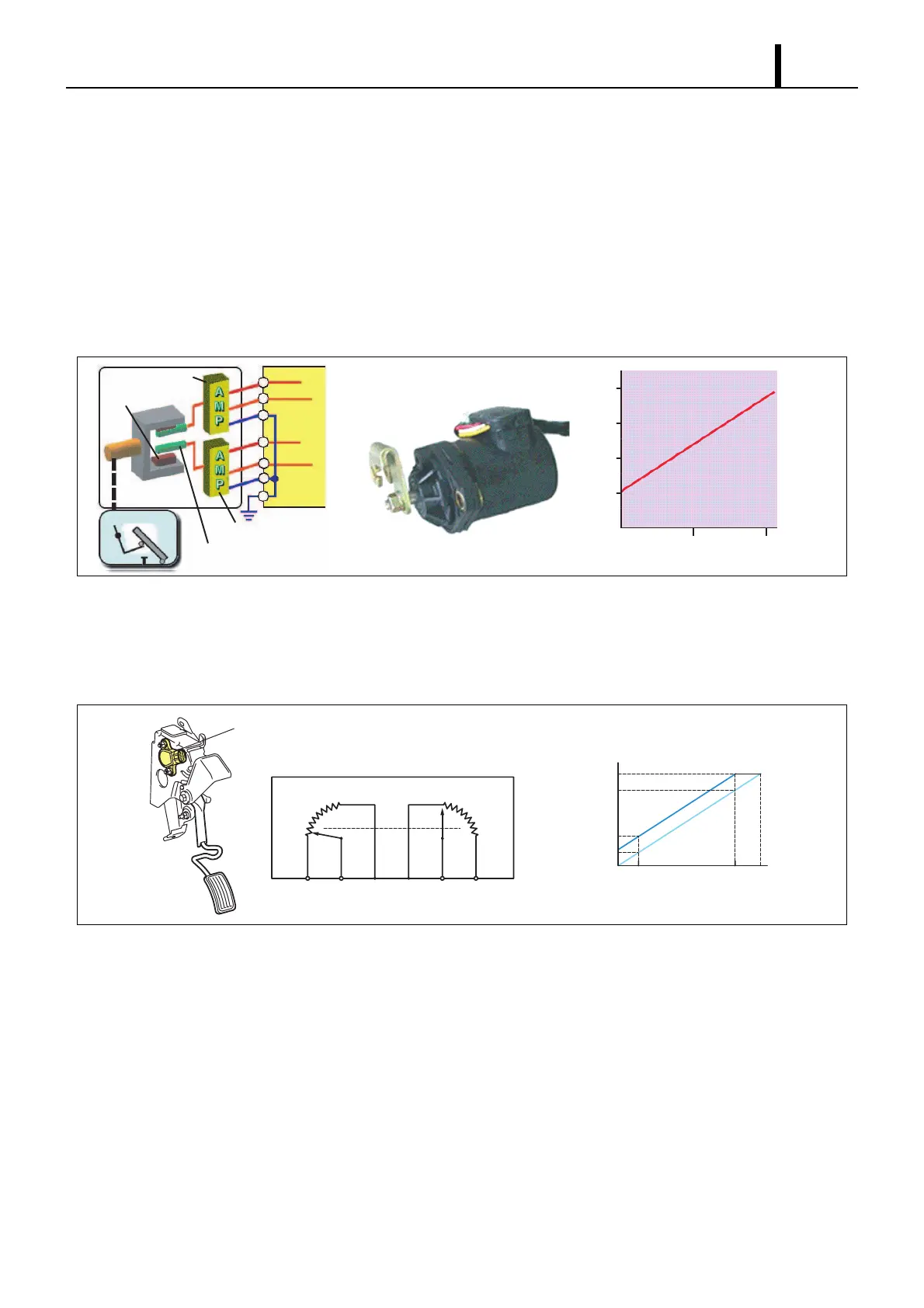
(2) Accelerator Position Sensor
• The accelerator position sensor converts the accelerator opening into an electric signal and outputs it to the engine
ECU. There are two types of accelerator position sensor: the hall element type and the contact type. In addition, to
provide backup in the event of breakdown, there are two systems and the output voltage is offset.
Hall Element Type
- This sensor uses a hall element to generate voltage from change in the direction of the magnetic field. A magnet
is installed on the shaft that rotates linked with the accelerator pedal, and the rotation of this shaft changes the mag-
netic field of the Hall element. The voltage generated by this change in the magnetic field is amplified by an amplifier
and input to the engine ECU.
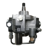
Contact Type
- The sensor uses a contact-type variable resistor. Since the lever moves linked with the accelerator pedal, the sen-
sor resistance value varies with the accelerator pedal opening. Therefore, the voltage passing the sensor changes,
and this voltage is input to the engine ECU as the accelerator opening signal.
Q000879E
4
3
2
1
0
50 100
VACCP Output Voltage (V)
Accelerator Opening (%)
Hall Elements (2)
Magnets (Pair)
Amplifier No. 1
Amplifier No. 2
+5V
+5V
A-VCC
A-VCC
VACCP1
VACCP2
A-GND
A-GND
ECU
Accelerator Pedal
VPA2
VPA1
EP2 VPA2 VCP2 EP1 VPA1 VCP1
Accelerator Position Sensor Circuit Diagram
Output Voltage
Accelerator Pedal Position
Accelerator Position Sensor
Fully Open
Fully Open
Fully
Open
Q000880E
Fully
Closed
Fully Closed
Fully Closed
Accelerator Position Sensor
Output Voltage Characteristic