www.desatech.com
116035-01J20
VENTING INSTALLATION
Continued
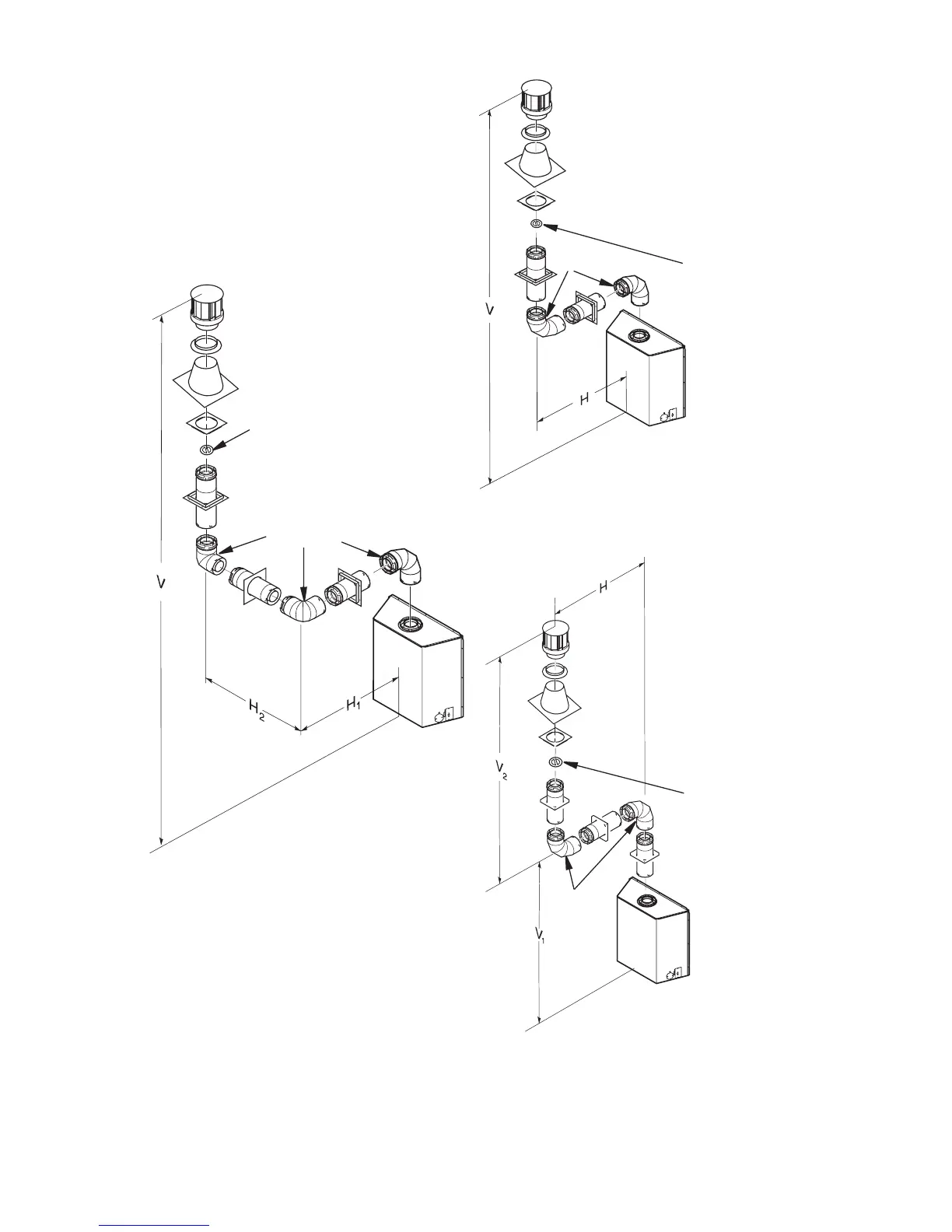
Figures 31 and 34 show four different congu-
rations for vertical termination.
VERTICAL VENT INSTALLATIONS USING
MULTIPLE 90° ELBOWS (V)CD36T TOP
VENT
Figure 33 - Vertical Venting
Conguration Using Two 90° Elbows
(Model (V)CD36T with Vertical Round
High Wind Termination)
Note: Vertical (V
1
) + Vertical (V
2
) = 40' Max.
Max. Horizontal Above 14' Vertical = 20'
Figure 31 - Vertical Venting
Conguration using Three 90° Elbows
(Model (V)CD36T with Vertical Round
High Wind Termination)
Horizontal
8' Min. 9' Max
9' Min. 11' Max
10' Min. 13' Max
12' Min. 17' Max
14' Min. 20' Max
Horizontal (H
Horizontal (H
8' Min. 5' Max
10' Min. 8' Max
12' Min. 11' Max
14' Min. 14' Max
16' Min. 17' Max
18' Min. 20' Max
40' Max. 20' Max
8' Min. 6' Max
9' Min. 8' Max
10' Min. 10' Max
12' Min. 14' Max
14' Min. 18' Max
40' Max. 20' Max
Note: Install a
VR-58 vertical
restrictor ring
into inner pipe
section prior to
attaching vent
termination cap.
90° Elbow
90° Elbow
Note: Install a
VR-58 vertical
restrictor ring
into inner pipe
section prior to
attaching vent
termination cap.
90°
Elbow
Note: Install a
VR-58 vertical
restrictor ring
into inner pipe
section prior to
attaching vent
termination
cap.
Figure 32 - Vertical Venting
Conguration Using Two 90° Elbows
(Model (V)CD36T with Vertical Round
High Wind Termination)