15
LT-2023
COMPONENT TESTING, REPAIR AND REPLACEMENT
To loosen the bib:
6. Remove the two screws (located directly above the hour meter) that hold
the bib to the unit’s internal structure. The bib can now be tilted forward to
allow access to the components behind it.
To remove the bib completely:
7. Disconnect the ribbon connector from the PC board.
8. Before disconnecting the wires from the power switch and circuit breaker
note their positions in order to reconnect them properly; then disconnect
the wires.
9. Tilt the top of the bib forward to release it from the slot in the body of the
concentrator.
10. Disconnect the hose at the bottom of the ow meter and remove bib.
11. To reassemble reverse steps 6 – 10 making sure bottom of front cabinet is
inserted securely in base of unit.
NOTE–The bib tab must be inserted into the slot above the rotary valve before
securing bib.
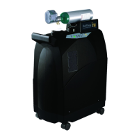
NOTE–All 525 models are now being built using Plastite cabinet screws. These
are special thread forming screws; so do not over tighten. They should be
torqued to 18 – 20 in-lbs. The original cabinet screw has much ner threads and
is not a thread forming screw.
These screws are not interchangeable, so be sure to order the correct part
number. See gure below.
Plastite Cabinet
Screw
Original Cabinet
Screw (525DD-628)
ACCUMULATOR PRESSURE TEST
To check accumulator pressures:
1. Make sure the unit is “Off.”
2. Use the Cabinet Removal instructions listed previously to open the unit for
testing.
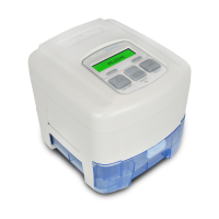
3. Use the pressure gauge (part #PVO2D-601) and pressure test assembly
(part #303DZ-637) included in the Service Kit.
Pressure Gauge
Pressure Test
Assembly
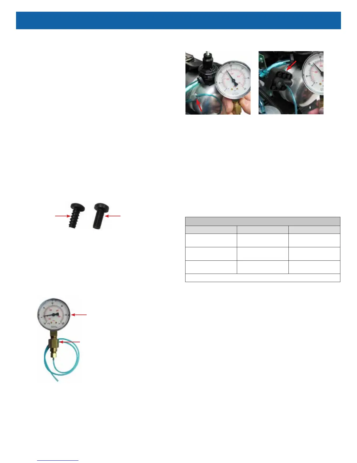
4. Remove the tubing cap from the accumulator tank tting or from the
manifold attached to the tank, and attach the 1/16" (1.6 mm) diameter
tubing from the gauge to the accumulator tank tting just vacated above.
See Figures below showing pressures being checked at accumulator tank "T"
tting and manifold.
ManifoldAccumulator "T" Fitting
5. Turn the unit “On” with the ow rate set to maximum recommended ow,
which is usually 5 lpm. Allow the unit to run for 5 minutes before observing
the pressures. During each timed cycle, the average pressure in the
oxygen accumulator will rise and fall. The high pressures should be
consistent and the low pressures should be consistent.
NOTE–Pressure drop will be 4-5 psi each cycle.
NOTE–Expected normal pressures observed depend on altitude and ow rate.
See the Expected Accumulator Tank Pressure Range chart below.
• Increases in altitude and ow rate will slightly decrease accumulator
pressures.
• Lower altitudes and ow rates will slightly increase accumulator pressures.
NOTE–A defective check valve, in either the purge harness or the manifold, may
cause a rapid drop in accumulator pressure below the minimum value.
EXPECTED ACCUMULATOR TANK PRESSURE RANGE @ 5LPM
Altitude Psi kPa
0 to 457 m
0 to 1500 ft.
23-32 159-221
457 to 914 m
1500 to 3000 ft.
21-29 145-200
914 to 1524 m
3000 to 5000 ft.
20-27 138-186
Includes a pressure drop of 4-5 psi and 27-34 kPa during the pressure cycle.
6. Refer to the Type 1 – Purity Issues, found under Simplied Troubleshooting,
to determine the appropriate action to take in resolving abnormal pressure
cycles.
NOTE–A defective compressor will be indicated by slowly rising pressure.
Pressure may only reach a certain level and then stop.
Low oxygen concentration levels and accumulator pressures higher than normal
may indicate defective sieve beds. Severely contaminated beds may also cause
the pressure relief valve on the compressor to open.
NOTE–A malfunctioning rotary valve may also cause high accumulator tank
pressure and activation of the pressure relief valve. In this case it should be
determined whether the problem is with the sieve beds, valve, or both.