LT-2023
18
COMPONENT TESTING, REPAIR AND REPLACEMENT
6. Lift compressor partially out of the compressor housing area and loosen
ladder clamp securing hose to the intake tting, then remove hose.
7. Compressor may now be removed from the compressor housing area.
CAUTION– If the unit has been running recently, the compressor may be hot.
8. Unscrew motor mounts from compressor feet by hand.
To inspect and/or replace internal
components:
1. Remove the eight screws that hold the compressor heads in place. When
removing the heads, be sure to keep each head and its components with
the correct compressor side.
2. Check for proper placement of or damage to the gaskets on the bottom of
the compressor heads. Replace if damaged.
3. Remove reed valve plates. A reed valve is located on each side of the
valve plate.
4. The compressor reed valves should be ush with the valve plate. If the
valve is broken or not ush with the valve plate, or foreign matter is
detected inside the head, clean or replace the compressor reed valves.
To replace the compressor reed valves:
a. Remove the screw holding the compressor reed valves in position on
the valve plate and discard the used reed valves.
b. Position the new reed valves so that they are centered and completely
cover the holes in the valve plate.
c. Place the metal retainer on the reed valves and secure with the reed
valve screw.
5. Check for proper placement of or damage to the rubber o-ring on the
bottom of the valve plate. Replace if damaged.
6. Remove piston sleeves by pulling upward and inspect cup seal on pistons.
Replace if badly worn or damaged.
To replace cup seal:
a. Remove rod screw from top of piston.
b. Remove the cup retainer plate.
c. Discard defective cup seal.
d. Place new cup seal into position.
e. Replace cup retainer plate.
f. Secure with screws.
7. Discard old sleeve and position new sleeve at 45 degree angle over the
piston. Carefully push it down as you rotate it slightly around the top of the
piston until it is in place.
8. Place valve plates on the compressor so that heads of reed valve screws
are aligned with the indentation in top of pistons.
9. Install the compressor heads so that the holes in the heads are aligned
with the holes in the compressor housing.
10. Secure compressor heads with the screws.
To replace the compressor:
CAUTION–The 525DS concentrators use a GSE compressor with a 22 mfd
capacitor. The 525KS/525PS concentrators use a GSE compressor with a 10 mfd
capacitor. If replacement is necessary, be sure the correct capacitor is installed.
1. Inspect the motor mounts. Replace if damaged. Attach mounts to
compressor feet.
2. Inspect the capacitor to determine if replacement is necessary. If capacitor
is wrong value for compressor or replacement is desired, refer to Capacitor
section.
3. Reconnect hose to the compressor intake tting.
4. Position compressor on the base of the unit so that the studs on the motor
mounts protrude through the holes in the base of the unit.
5. Secure motor mounts with hex nuts.
6. Reconnect hoses to the ttings at compressor exhaust and lter.
7. Reconnect the compressor electrical connector.
COOLING FAN
The cooling fan provides a constant air ow to cool the compressor. The cooling
fan is located in the bottom of the unit below the compressor.
A defective cooling fan may cause the compressor’s internal thermo-protective
(thermal cut off) device to activate and shut the compressor off. Should this
condition occur, the compressor will require several minutes for the thermo-
protective device to reset.
If the cooling fan is defective, it must be
replaced:
1. Make sure the unit is unplugged from the wall outlet.
2. Use the Cabinet Removal instructions listed previously to open the unit.
3. Use the To Remove the Compressor instructions listed under Compressor.
4. Disconnect the cooling fan terminals.
5. Note the position of the fan and fan guard before removing the four
retaining screws that secure the fan to the base of the unit.
6. Remove the defective fan and secure the replacement fan in position with
the four retaining screws.
NOTE–When installing the fan, be sure the air ow directional arrow on the side
of the fan is directed away from the compressor and fan guard is reinstalled
properly.
7. Reconnect the electrical connector.
8. Reinstall the compressor.
FLOW METER
There are two ow meters available for the DeVilbiss 525 series oxygen
concentrators: a standard 5 lpm ow meter (505DZ-607) and a low output ow
meter (515LF-607). The low output ow meter should be used when the
prescribed ow rate is at or under 1 lpm.
NOTE–Installation of a low output ow meter eliminates the low ow alert for ow
delivery under 0.5 lpm.
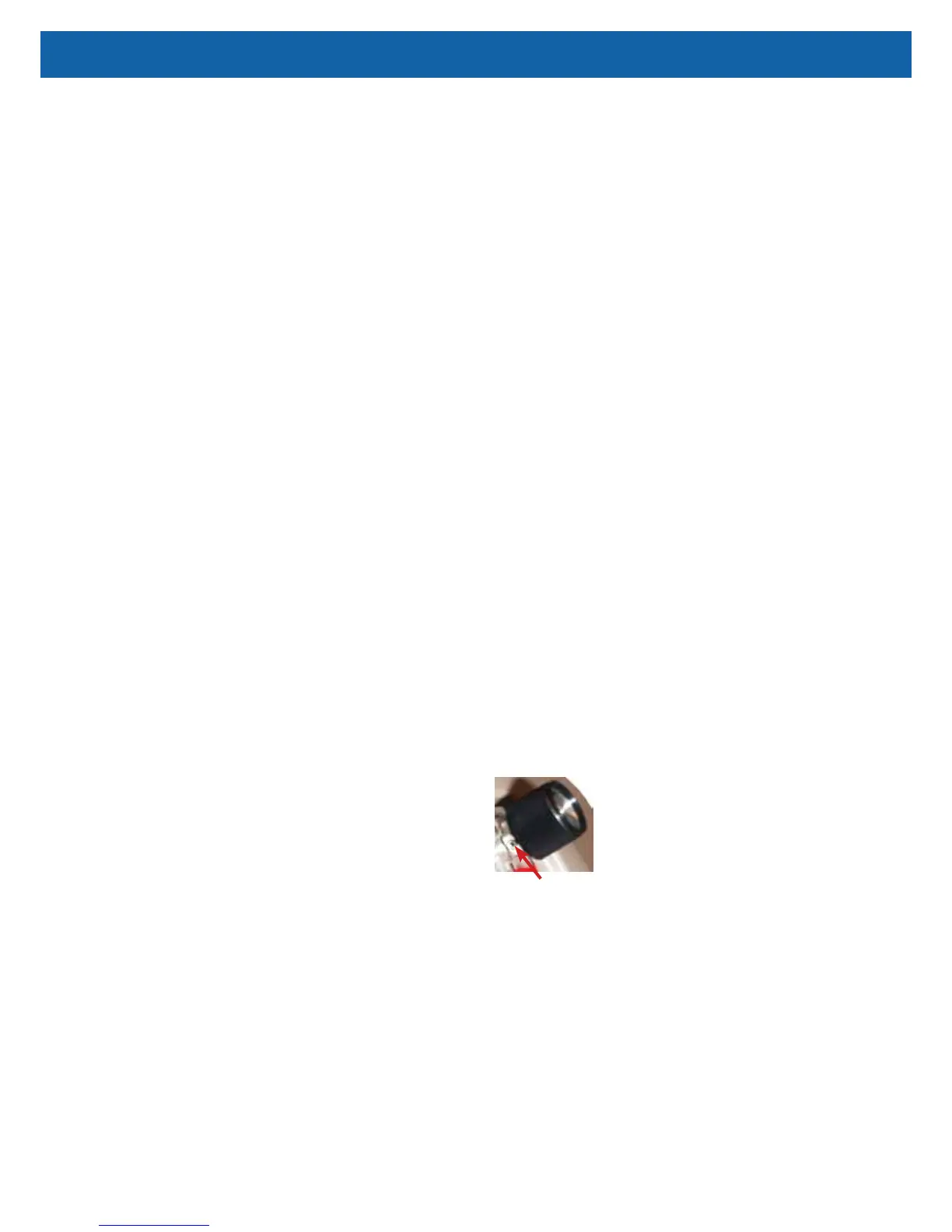
Locking Screw
Both pressure-compensated ow meters have an accuracy
level of ±5% at full scale (exception: +0% / -5% at 5 lpm)
and are designed for use at 8.5 psi (58.6 kPa). Both ow
meters can be locked using a 1/16th inch Allen wrench and
tightening the locking screw behind the ow meter knob.
To check for leaks in the flow meter tubing:
1. Check for leaks using a certied leak detection solution such as Snoop® or
equivalent (must not contain ethylene glycol).
2. Apply leak test solution to all ttings and hose connections with the unit
running.
CAUTION–Do not apply leak test solution to any part of the rotary valve or the
main PC Board assembly.
3. I f an air leak is present, the solution will bubble. All leaks should be
repaired before putting the concentrator back in service.
WARNING
Electric Shock Hazard. Use caution when leak testing near electrical
connections.