LT-2023
20
COMPONENT TESTING, REPAIR AND REPLACEMENT
MOLECULAR SIEVE BEDS
The build and release of pressure in the sieve beds indicates the health of the
sieve material and the operation of contributing components. Determine ‘good’ or
expected pressures for your altitude by testing bed pressures on multiple oxygen
concentrators that are producing at least 93% purity.
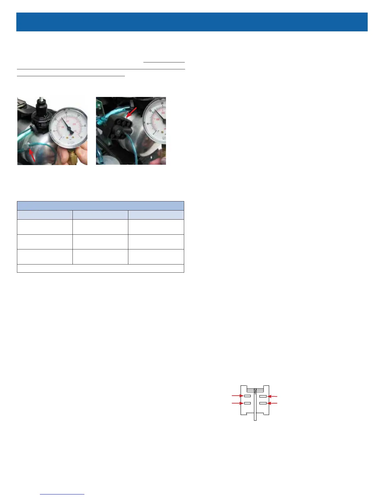
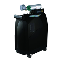
Check sieve bed pressures at the accumulator tank using the manifold test point
or the accumulator tank test point. See Figures below.
ManifoldAccumulator "T" Fitting
NOTE–The pressure will rise and fall as it cycles through the rotary valve.
Also consider the acceptable pressure range for various altitudes as shown
below.
EXPECTED ACCUMULATOR TANK PRESSURE RANGE @ 5 LPM
Altitude Psi kPa
0 to 457 m
0 to 1500 ft.
23-32 159-221
457 to 914 m
1500 to 3000 ft.
21-29 145-200
914 to 1524 m
3000 to 5000 ft.
20-27 138-186
Includes a pressure drop of 4-5 psi and 27-34 kPa during the pressure cycle.
To test sieve bed pressures:
1. Remove the plugged piece of 1/16" tubing from the manifold or the
accumulator tank.
2. Connect the pressure gauge to the test point and observe the cycling of
pressures. Refer to the section on Normal Operating Sequence and also
Accumulator Pressure Test.
a. If it is determined that the valve is not cycling the pressure, refer to
the section on Rotary Valve testing.
b. If the unit is cycling properly, allow it to operate for 20 minutes.
3. After 20 minutes of operation, observe the high and low pressures and
check the oxygen concentration level.
a. If the pressures are within the expected range and the oxygen
concentration is within specication, the sieve material is effective.
b. If pressures are not within the expected range and/or the oxygen
concentration is not within specication, refer to the Simplied
Troubleshooting Table in this manual to determine the proper
corrective action.
NOTE–If the molecular sieve material is found to be no longer effective, rst
search for the source of a malfunction in the system; then, for a cause for
contamination (such as leaks) and take corrective action.
To replace the molecular sieve beds:
NOTE–Make sure that the sealing caps remain on the new sieve beds until just
prior to connecting hoses and tubing.
1. Ensure any contamination problem has been corrected.
2. Ensure the unit is unplugged from the wall outlet.
3. Cut the plastic cable ties that secure the sieve beds to the internal structure
of the unit.
4. Remove the tubing from the ttings at the top of each sieve bed.
5. Remove the hose clamps and hose from the bottom of the sieve beds.
6. Install new sieve beds in reverse order using new plastic cable ties.
Position the new beds so that the bed serial number label is at the top of
the unit.
7. Leak test all connections with a certied leak detection solution such as
Snoop® or equivalent (must not contain ethylene glycol). Apply leak test
solution to all ttings and hose connections with unit running. If an air leak
is present, the solution will bubble. All leaks should be repaired before
putting the unit back in service.
CAUTION–Do not apply leak test solution to any part of the rotary valve or the
main PC Board assembly.
POWER CORD
To replace the power cord - 115 volt units
only:
1. Make sure the unit is unplugged from the wall outlet.
2. Use the Cabinet Removal instructions listed previously to open the unit.
3. Disconnect the power cord connector.
4. Note wire colors and socket locations before removing wires.
5. Using a pair of duckbill pliers, squeeze the power cord strain relief and pull
it out of the base of the unit.
6. Insert a new power cord through the hole in the base of the unit and secure
with strain relief.
7. Insert sockets into connector housing and then reconnect the power cord
connector.
8. Replace back cabinet and secure with the six screws.
POWER SWITCH
To replace the power switch:
1. Make sure the unit is unplugged from the wall outlet.
2. Use the Cabinet Removal instructions listed previously to open the unit.
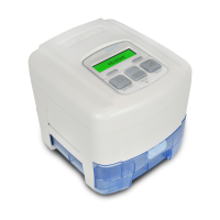
3. Note the position of the wires and switch before removing the wires from
the switch terminals.
4. While squeezing the locking tabs on the sides of the switch, push the
switch out of the front of the unit.
5. Install the new switch in the correct orientation making sure that it locks into
position.
6. Reconnect the wires to the switch terminals.
Brown Wire (or 2 Black Wires)
2 Black Wires (or 1 Brown Wire)
*Red Wire
*Red Wire
* Either red wire can be connected to either left hand terminal of the switch
Switch Detail