19
LT-2023
COMPONENT TESTING, REPAIR AND REPLACEMENT
To replace the flow meter:
1. Make sure the unit is unplugged from the wall outlet.
2. Use the Cabinet Removal instructions listed previously to open the unit.
3. From behind the bib/front cabinet, remove the 2 hoses from the ow meter.
4. While squeezing tabs on ow meter brackets, push the ow meter through
the bib/front cabinet or just unscrew ow meter ttings.
5. Install new ow meter and reconnect hoses.
To install or replace the low output flow
meter:
1. Ensure that the unit is unplugged from the wall outlet.
2. Use the Cabinet Removal instructions listed previously to open the unit.
3. Disconnect:
a. All wires, terminals and connectors attached to the PC board.
b. The 1/8 ID blue tubing from the Oxygen Sensing Device (OSD) and
from the ow meter.
c. The screw that secures the PC board to the unit.
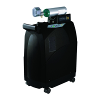
4. Build the T-tting assembly. (Skip this step, if replacing an existing low
output ow meter.)
a. Cut the existing 1/8 inch blue tubing that connected the OSD and the
ow meter into two equal pieces.
b. Attach each piece of the cut tubing to the large ends of the T-tting,
included in the kit.
c. Attach one end of the 1/16 inch ID blue tubing, included in the kit, to
the small end of the T-tting.
5. Position the bleed-off orice and connect tubing.
21
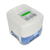
Insert an opened paperclip through the hole in the case, behind where the PC board
was installed (Fig. 1), until it appears in the lter cavity (Fig. 2).
Place the orice tting, included in
the kit, onto the end of the paperclip
(Fig. 3).
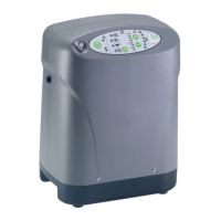
Push the tting through the foam
until it’s inside the case. Remove
the paperclip and attach the 1/16
inch ID tubing (Fig. 4).
3 4
6. Replace the ow meter.
a. Remove all tubing from the current ow meter.
b. Unscrew white plastic connectors or ttings.
c. Remove the metal brackets and push the meter through the case.
Save the meter and metal brackets for later use, if desired.
d. Align the new metal brackets on the at surfaces of the new meter.
e. Push the ow meter into the case with the highest ow at the top.
7. Reassemble the unit.
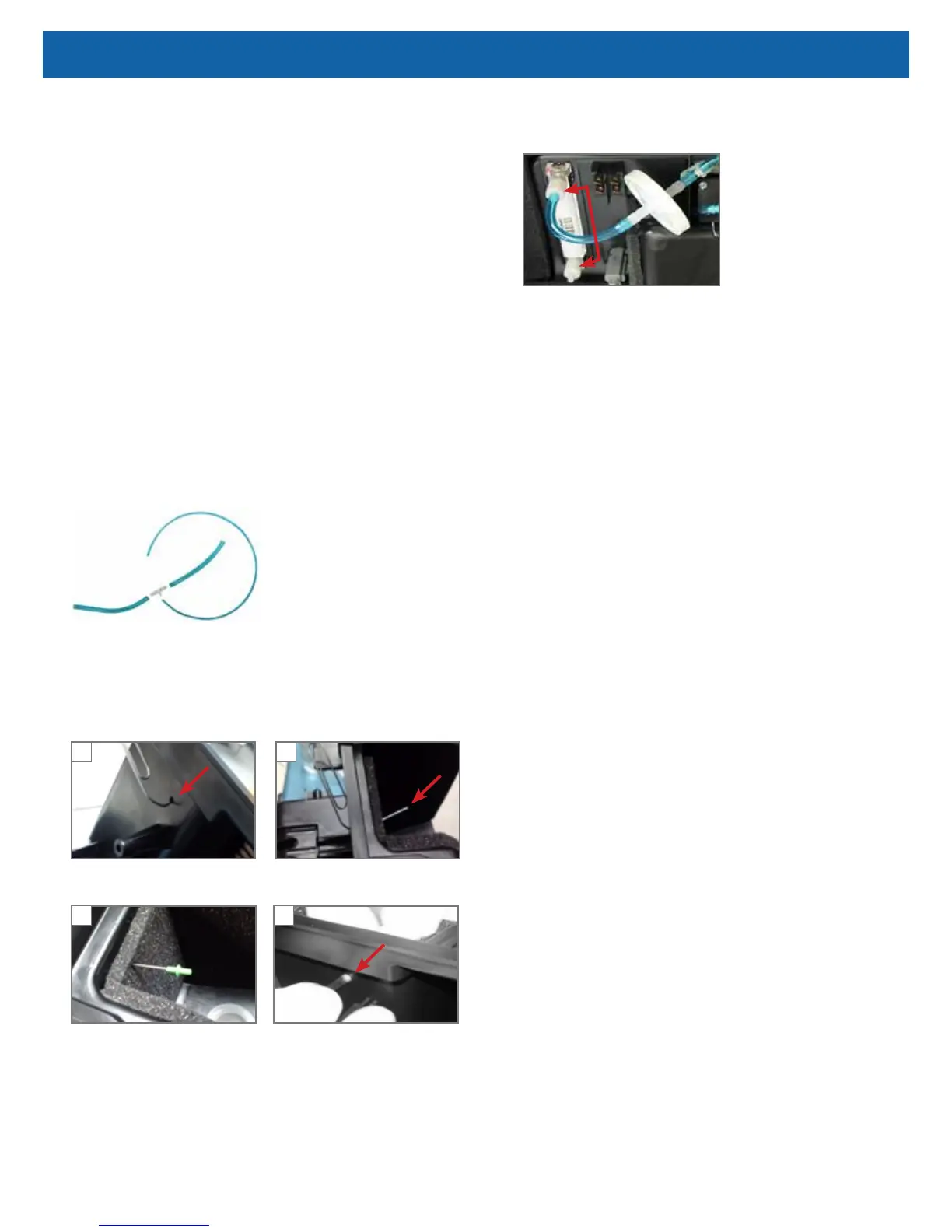
a. Connect one end of the 1/8 inch blue tubing to the T-tting assembly
to the bottom of the ow meter and the other end to the bottom of the
OSD.
b. Reconnect the PC board wires, tubing, terminals and connectors.
HOUR METER
To replace the hour meter:
1. Make sure the unit is unplugged from the wall outlet.
2. Use the Cabinet Removal instructions listed previously to open the unit.
3. Remove PC board.
4. Squeeze locking tabs on both sides of hour meter while pushing upward to
remove meter.
5. Install a new hour meter by applying downward pressure until it snaps into
position.
6. Replace PC board and reconnect all wires, connectors and tubing.
CAUTION–Do not apply any force or ex the PC Board when connecting or
disconnecting electronic or pneumatic components. Damage to the electronic
assembly is possible.
MANIFOLD
The manifold is attached to the accumulator tank and performs the same function
as a purge harness. It directs a small amount of pressurized oxygen into the
discharging sieve bed to aid the nitrogen exhaust process while it ensures that
the majority of pressurized oxygen is directed into the accumulator tank. The
manifold also prevents reverse ow of oxygen from the accumulator to the sieve
beds.
See CHECK VALVES: MANIFOLD and SIEVE in this manual for additional
information.