LT-2023
16
COMPONENT TESTING, REPAIR AND REPLACEMENT
AUXILIARY OXYGEN PORT
All 525 series concentrators are now being manufactured with an auxiliary
oxygen port located on the back of the unit. Concentrators with the auxiliary port
have serial numbers starting with “N” or “R”.
To ll oxygen cylinders:
This external port can be used to ll oxygen cylinders with an FDA-cleared
cylinder lling device that is designed to use oxygen from a concentrator to ll a
cylinder. The port is only for use with FDA-cleared lling devices with compatible
oxygen input specications.The ow meter should be set at 3 LPM or less when
the concentrator is being used during cylinder ll. The port does not affect
concentrator performance if properly used. See gures below.
Auxiliary Port Output Specications:
Outlet Pressure .................................. 8.5
±0.5 psi
Outlet Flow ...................................... 2.5
±0.5 LPM
Outlet Oxygen ..............................................>90%
Operation Time ................................... Continuous
Refer to the cylinder lling device instruction guide for the oxygent input/output
specications, connection and operating instructions.
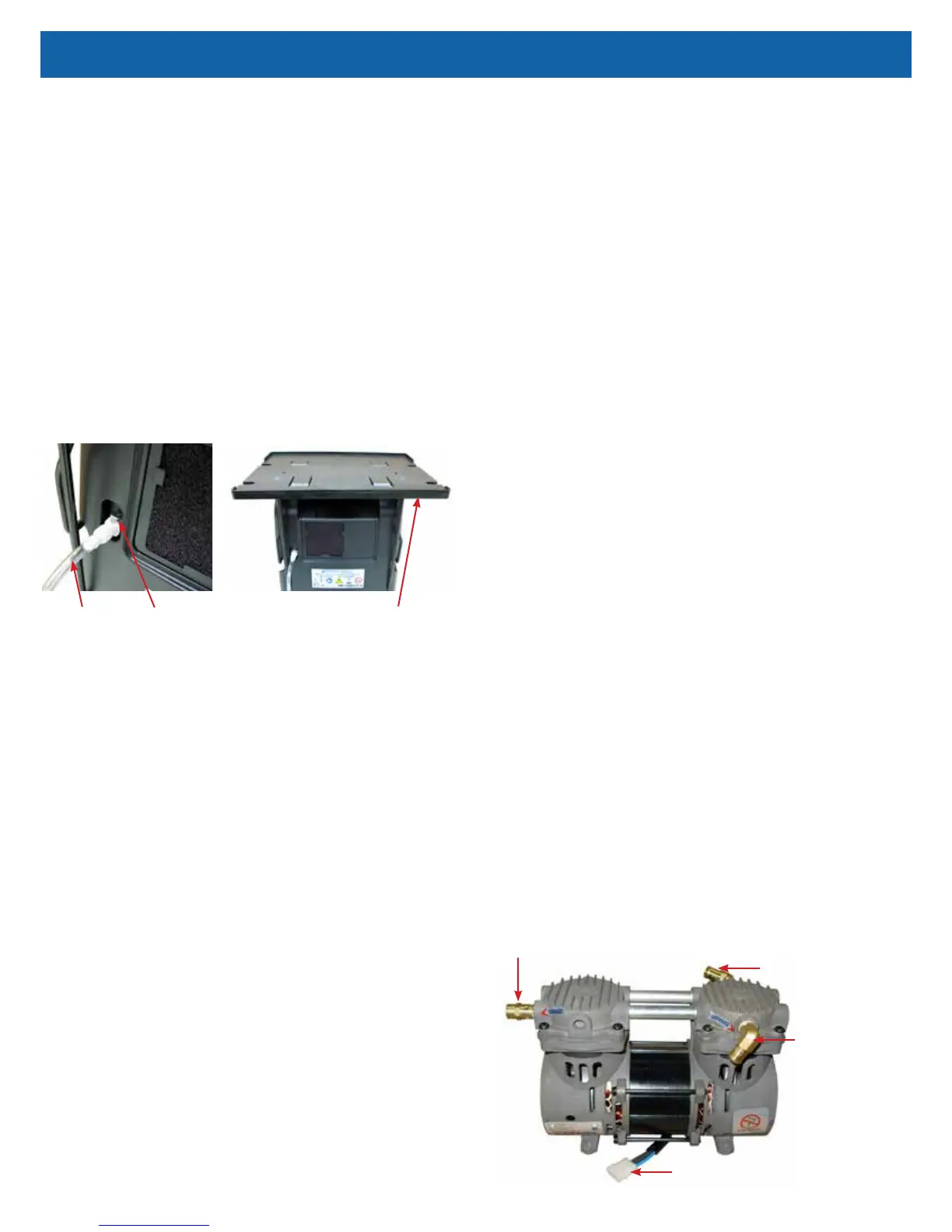
Transfill Hose
(PF1100TUB)
Auxiliary Port
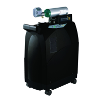
Transfiller Caddy
(525DD-650)
CAPACITOR
The capacitor enables the compressor to start and run by supplying voltage to
the windings of the compressor motor. A defective capacitor will result in the
compressor running slower or not starting.
CAUTION–The 525DS concentrators use a GSE compressor with a 22 mfd
capacitor. If replacement is necessary, be sure the correct capacitor is installed.
CAUTION–The 525KS/525PS concentrators use a GSE compressor with a 10
mfd capacitor. If replacement is necessary, be sure the correct capacitor is
installed.
WARNING
Electric Shock Hazard. When replacing the capacitor, do not touch the
terminals or allow metal objects to come in contact with the terminals on
the capacitor. The capacitor may hold a charge for several days after the
unit is turned off.
If a defective capacitor is suspected, a new one must be installed. The capacitor
is strapped into a well molded into the bottom of the unit next to the cooling fan.
To replace the capacitor:
1. Make sure the unit is unplugged from the wall outlet.
2. Remove the back cabinet. Use the Cabinet Removal instructions listed
previously.
3. Remove the compressor. Use the To Remove the Compressor instructions
listed under Compressor.
4. Disconnect the two wires from the terminals on the capacitor.
5. Cut the nylon cable tie holding the capacitor in place and remove the
capacitor.
6. Reconnect the wires to the new capacitor.
7. Install the new capacitor and secure with a new cable tie.
8. Replace the compressor and reassemble cabinet.
9. Replace the back cabinet and secure with the six screws.
CHECK VALVES/MANIFOLD
Manifold And Sieve Bed Check Valves
The manifold check valves, located in the manifold attached to the accumulator
tank, and the sieve bed check valves, located in the purge harness, between the
outlet of each sieve bed and the accumulator tank, allow oxygen to pass from the
sieve beds to the accumulator tank, when the bed pressure is greater than the
accumulator tank pressure. These valves also prevent reverse ow of oxygen
from the accumulator tank to the sieve beds.
The manifold also directs a small amount of pressurized oxygen into the
discharging sieve bed to aid the nitrogen exhaust process. The purge harness
includes a xed orice that performs the same function.
A defective manifold or sieve bed check valve will result in lower oxygen
concentrations and accumulator pressures.
Use the Accumulator Pressure Test described in this section to troubleshoot
manifold or sieve bed check valves.
• To replace a defective sieve bed check valve, remove the tubing on either
side of it and install a new valve making sure the outlet end is toward the
accumulator tank.
• To replace a defective manifold check valve, replace the manifold.
NOTE– Also see manifold section on page 19.
Final Check Valve
The nal check valve is located, on older units, between the nal bacteria lter
and the oxygen outlet tting.
To replace the nal check valve:
1. Make sure the unit is unplugged from the wall outlet.
2. Use the Cabinet Removal instructions listed previously to open the unit.
3. Remove the hose from the outlet side of the nal bacteria lter.
4. Remove the two screws from the back of the oxygen outlet tting assembly
and remove the assembly.
5. Remove the hose from each end of the nal check valve.
6. Attach the hoses to a new check valve. Make sure that the at side of the
check valve is directed toward the oxygen outlet tting.
7. Replace the outlet tting assembly and connect the hose to the lter.
8. Reassemble the cabinet.
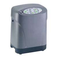
COMPRESSOR
The DeVilbiss Oxygen Concentrator uses a double-head, oil-free compressor.
The compressor is secured to the base with four motor mounts.
Electrical Connector
Exhaust Fitting
Intake Fitting
Pressure Relief Valve