17
LT-2023
COMPONENT TESTING, REPAIR AND REPLACEMENT
A compressor that is worn or defective may:
• cause pressure to rise slowly.
• cause excessive noise and/or vibration.
• cause lower oxygen concentrations.
A worn or defective compressor can be caused by a defective internal
component such as:
• reed valve
• o-ring
• gasket
• cup seal
These components are included in the Compressor Rebuild Kit (525D-643 and
525K-643).
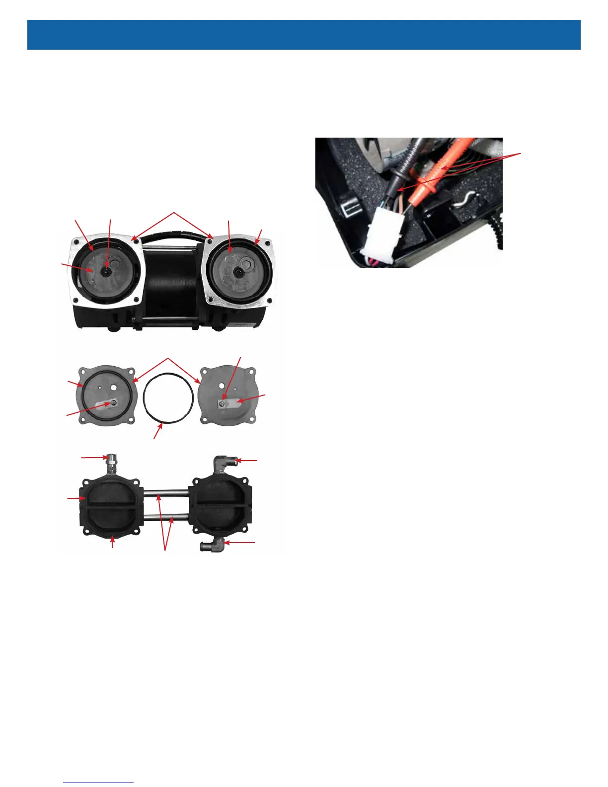
Sleeve
Valve Plate
Rod Screw
Rod (beneath
cup retainer)
Cup Seal
Cup
Retainer
Reed
Valve or
Flapper
Retainer
Intake
Fitting
PR Valve
Compressor
Head
Head
Gasket
Screw
Connecting
Tubes
O-Ring
Spacer
Sleeve
Exhaust
Fitting
NOTE–A built-in thermal cutoff switch will shut the compressor off if it becomes
overheated. This protects the compressor from damage caused by heat build-up.
(Some models have an auxiliary thermostat mounted within the compressor
compartment.) Should this condition occur, the compressor will require several
minutes for the thermo-protective device to reset.
NOTE–A pressure relief (PR) valve is located on the pressure head to prevent
high pressure build up in the system should a component malfunction occur.
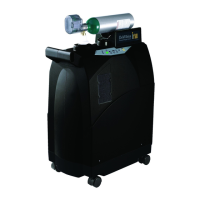
To test the compressor operating voltage:
The compressor requires line voltage to operate. If the compressor does not start
when the unit is turned on, the voltage input must be tested:
1. This voltage can be checked at the compressor connector using a
voltmeter or test light connected to the brown and blue wires. The voltmeter
is the best way to test.
Testing Compressor Voltage
Voltmeter Leads
2. If no voltage is detected, disconnect power and check for loose or broken
wires between the compressor connector and switch or wire harness.
3. If there is voltage at the compressor connector, then either the capacitor or
the compressor itself is defective.
To test the compressor for proper output:
NOTE–If the compressor is not providing a high enough output the patient alert
system may be activated.
1. Use the Cabinet Removal instructions listed previously to open the unit for
testing.
2. Use the Accumulator Pressure Test listed previously to observe the high
pressures, low pressures and the pressure drop.
3. Refer to the Type 1 – Purity Issues, found under Simplied Troubleshooting,
to determine the appropriate action to take in resolving abnormal pressure
cycles.
NOTE–A compressor, which slowly builds pressure that remains below 25 psi,
indicates worn cup seals and/ or reed valves.
If these conditions are observed then:
• The unit lter(s) may be occluded—check the air lter, compressor lter,
and intake lter for occlusions.
• There may be a severe leak in the system—check for air leaks using a leak
detection solution such as Snoop
®
or equivalent (must not contain ethylene
glycol).
CAUTION–Do not apply leak test solution to any part of the rotary valve or the
main PC Board assembly.
• The compressor reed valves, cup seal, or the compressor itself may be
defective.
If the lters are not occluded and no leaks are found, the compressor must then
be removed and repaired or replaced.
To remove the compressor:
1. Make sure the unit is unplugged from the wall outlet.
2. Use the Cabinet Removal instructions listed previously to open the unit.
3. Disconnect the compressor wires by disconnecting the compressor
electrical connector.
4. Remove the ladder clamp and hose from the exhaust ttings on the
compressor head and compressor lter if applicable.
5. Carefully place the concentrator on its front side. From the bottom of the
unit, remove the four 10 mm hex nuts that secure the motor mounts.