LT-2023
22
COMPONENT TESTING, REPAIR AND REPLACEMENT
b. If it is determined that the valve did not shift properly or the high
pressures or low pressures are uneven, continue testing with step 3.
3. The stepper motor on the rotary valve has multiple windings so there are
several voltage readings that need to be checked in order to determine if
the problem is being caused by the PC board or the valve itself. Testing for
proper voltage is done at the wire harness connectors on the valve or on
the PC Board using a voltmeter.
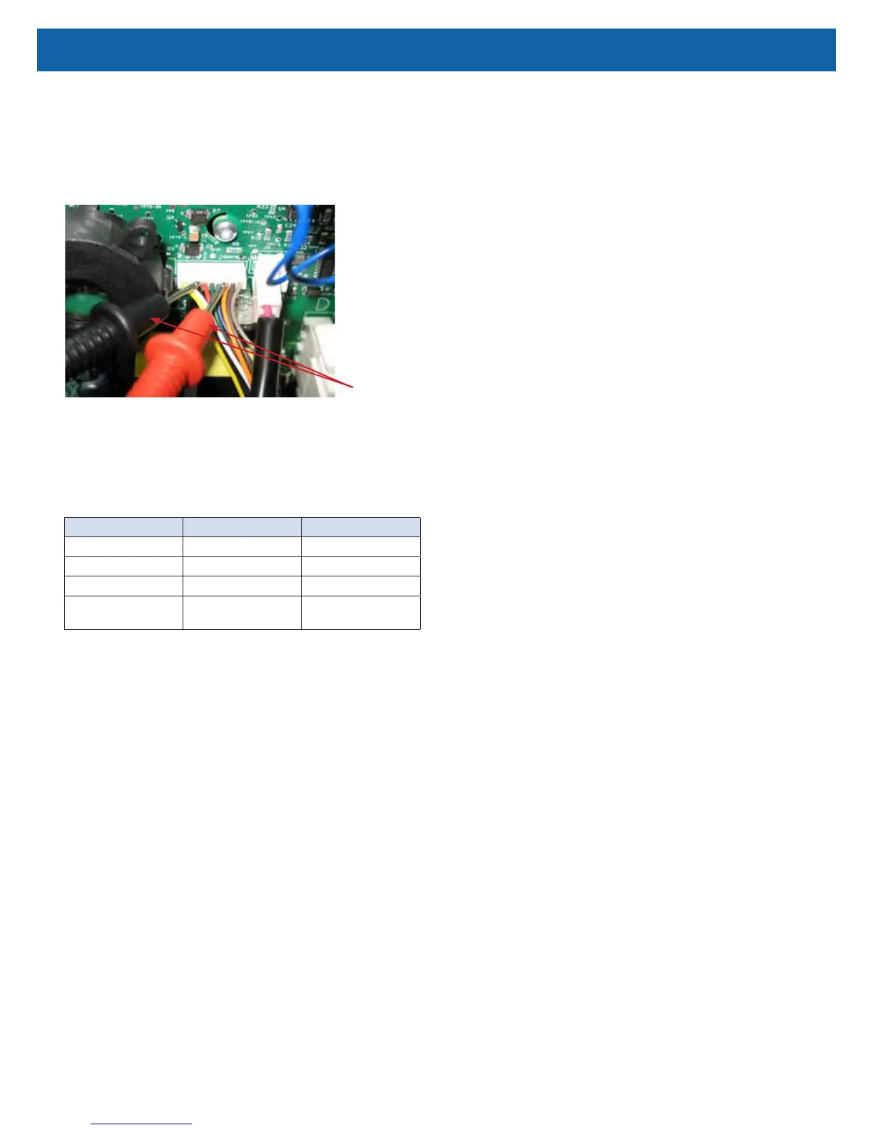
Testing Valve Voltage at PC Board
Voltmeter
Leads
Below are the valve voltage test positions and voltages that should be present at
each one:
NOTE–The 1-3 Volt reading will go on and off as the valve cycles. 525
Series have a xed cycle time of 3.6 seconds @5 LPM. However, when the
concentrator goes into its “turn-down” mode, the cycle time is shortened.
Negative Lead Positive Lead Voltage Reading
Orange Yellow or White 12 VDC
Orange Gray 5 VDC
Orange Brown 5 VDC (intermittent)
Black or Green or Red
or Blue
Yellow or White 1-3 VDC (intermittent)
a. If any of these readings are not obtained, check for loose or broken
wires in the harness. If wire harness is okay, replace the main PC
board.
b. If proper voltages are obtained, replace valve.
To replace the rotary valve:
1. Make sure the unit is unplugged from the wall outlet.
2. Use the Cabinet Removal instructions listed previously to open the unit.
3. Unplug valve wire harness from the valve.
4. Loosen clamps and remove bed hoses from each side of valve.
5. Loosen ladder clamps and remove pressure intake and exhaust hoses from
backside of valve.
6. Install the new rotary valve by reversing the above procedure.