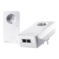
EasyManuals Logo

Devolo Magic2 LAN DINrail User Manual

Devolo Magic2 LAN DINrail
39 pages
To Next Page IconTo Next Page
To Previous Page IconTo Previous Page
Page #15 background imageLoading...
Page #15 background image
15 Introduction
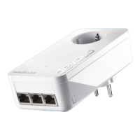
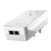
devolo Magic 2 LAN DINrail
3 Red LED Lights up stea-
dy
Status 1:
The other network nodes are in standby
mode and cannot currently be accessed over
the mains supply. The PLC LEDs of the other
devolo Magic adapters flash white only for a
short time.
Status 2:
The connection to the other network nodes
has been interrupted. There may be electro-
magnetic or radio frequency interference on
the power line. In this case, put the
devolo Magic adapters closer to each other
or try to shut off the source of interference.
Can be disabled
4Red and
white
LED
Red: flashes at
intervals of
0.25 sec. on/
2sec. off.
White: flashes
at intervals of
2sec. on/
0.25 sec. off
Data transmission rate not in optimum
range
Can be disabled
PLC-LED Flashing be-
haviour
Meaning LED status display
(web interface*)

Questions and Answers:

Question and Answer IconNeed help?

Do you have a question about the Devolo Magic2 LAN DINrail and is the answer not in the manual?

Devolo Magic2 LAN DINrail Specifications

General IconGeneral
Product TypePowerline adapter
Maximum Data Transfer Rate2400 Mbps
Operating Temperature0°C to 40°C
MountingDIN rail
Encryption128-bit AES
Frequency Range2-86 MHz
Operating Frequency50/60 Hz
Device TypePowerline
Operating Voltage100-240 V
Storage Temperature-25°C to 70°C
Humidity10-90% non-condensing
CertificationsCE, RoHS
StandardsHomePlug AV2, IEEE 1901

Related product manuals