10
1.5˝ (3.8 cm)
Hose from vacuum
system (not included)
Exhaust Tube
2˝ (5 cm)
Hose from
vacuum system
(not included)
(30563A)
2˝ (5 cm) Tube x 1.5˝
(3.8 cm) hose adapter
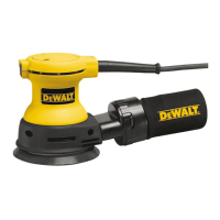
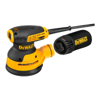
This sanding machine is designed to be operated with a remote
vacuum dust collection system or with the included dust bag.
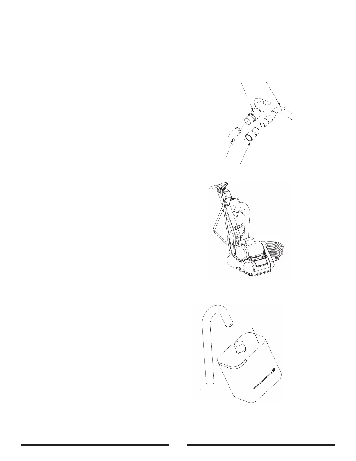
Preparing Remote Vacuum Dust Collection Systems
To prepare the machine for remote vacuum dust collection systems that
have a 2˝ (5 cm) hose end, follow this procedure:
1 Install 2˝ (5 cm) hose end (Figure 9, A) directly over the exhaust tube
(Figure 9, B).
2 The exhaust tube can be rotated for optimum convenience.
To prepare the machine for remote vacuum dust collection systems that
have a 1 ½˝ (3.8 cm) hose end, follow this procedure:
1
Install the 2˝
(5 cm)
x 1½˝
(3.8 cm)
hose end adapter (Part No. 30563A)
(Figure 9, C)
over the exhaust tube (Figure 9, B).
2 Insert 1 ½˝ (3.8 cm) hose end (Figure 9, D) into the adapter
(Figure 9, C).
NOTE: Start the remote vacuum collection system before operation.
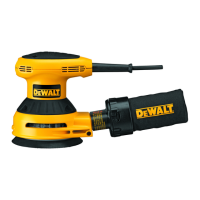
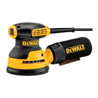
Preparing to use the included dust bag
To prepare the machine for use with the included dust bag
(Part No. AS104700), follow this procedure:
1. Install the dust bag by pressing the end onto the exhaust tube until
the ring locks into the groove (Figure 10). This is best done by
pressing on the back of the bag opening with the palm of your
hand.
2. The exhaust tube can be rotated for optimum convenience.
3. To remove the dust bag from the exhaust tube, pry up the end of
the bag opening to partially release the internal rib from the groove,
then pull.
4. To empty the dust bag, unzip the disposal ap and force contents
out by inverting the bag.
NOTE: For best results, empty frequently. Follow all warnings posted
in
this manual and on the dust bag.
Install the dust bag by
pressing the end onto
the exhaust tube until
the ring locks into the
groove.
B
C
A D
ENGLISH
MACHINE SETUP
Figure 9
Figure 10