35
ENGLISH
5. Proceed as for a vertical straight cross-cut.
Quality of Cut
The smoothness of any cut depends on a number of variables, i.e. the
material being cut. When smoothest cuts are desired for moulding
andother precision work, a sharp (60-tooth carbide) blade and a slower,
even cutting rate will produce the desiredresults.
WARNING: Ensure that the material does not creep while cutting;
clamp it securely in place. Always let the blade come to a full stop
before raising the arm. If small fibres of wood still split out at the rear
of the workpiece, stick a piece of masking tape on the wood where
the cut will be made. Saw through the tape and carefully remove tape
whenfinished.
Cutting Non-Ferrous Metals
When cutting non-ferrous metals, the machine is only to be used to
perform vertical straight and mitre cross-cuts in the mitre saw mode.
We recommend that bevel and compound mitre cuts should not be
performed in non-ferrous metals. The machine is not to be used for cutting
ferrousmetals.
• Always use a material clamp when cutting non-ferrous metals. Make
sure that the workpiece is clamped securely.
• Only apply saw blades that are qualified for cutting non-ferrous metals.
• When using lubricants, only apply wax or separation spray. Do not use
emulsions or similar fluids.
Clamping the Workpiece (Fig. U)
WARNING: Always use a materialclamp.
For best results use the material clamp
17
made for use with yoursaw.
To Install clamp
1. Insert it into the hole behind the fence. The clamp
17
should be facing
toward the back of the mitre saw. Ensure the groove on the clamp rod
is fully inserted into the base of the mitre saw. If the groove is visible,
the clamp will not besecure.
2. Rotate the clamp 180º toward the front of the mitresaw.
3. Loosen the knob to adjust the clamp up or down, then use the fine
adjust knob to firmly clamp theworkpiece.
NOTE: Place the clamp on the right side of the base when beveling.
ALWAYS MAKE DRY RUNS (UNPOWERED) BEFORE FINISH CUTS TO CHECK
THE PATH OF THE BLADE. ENSURE THE CLAMP DOES NOT INTERFERE WITH
THE ACTION OF THE SAW ORGUARDS.
Compound Mitre (Fig. S, T)
This cut is a combination of a mitre and a bevel cut. This is the type of cut
used to make frames or boxes with slanting sides like the one shown in
figureS.
WARNING: If the cutting angle varies from cut to cut, check that
the bevel clamp handle and the mitre clamping knob are securely
tightened. These must be tightened after making any changes in bevel
ormitre.
WARNING: The saw must be fixed on a base support when
performing compound cuts to prevent tip over. Refer to Bench
Mounting.
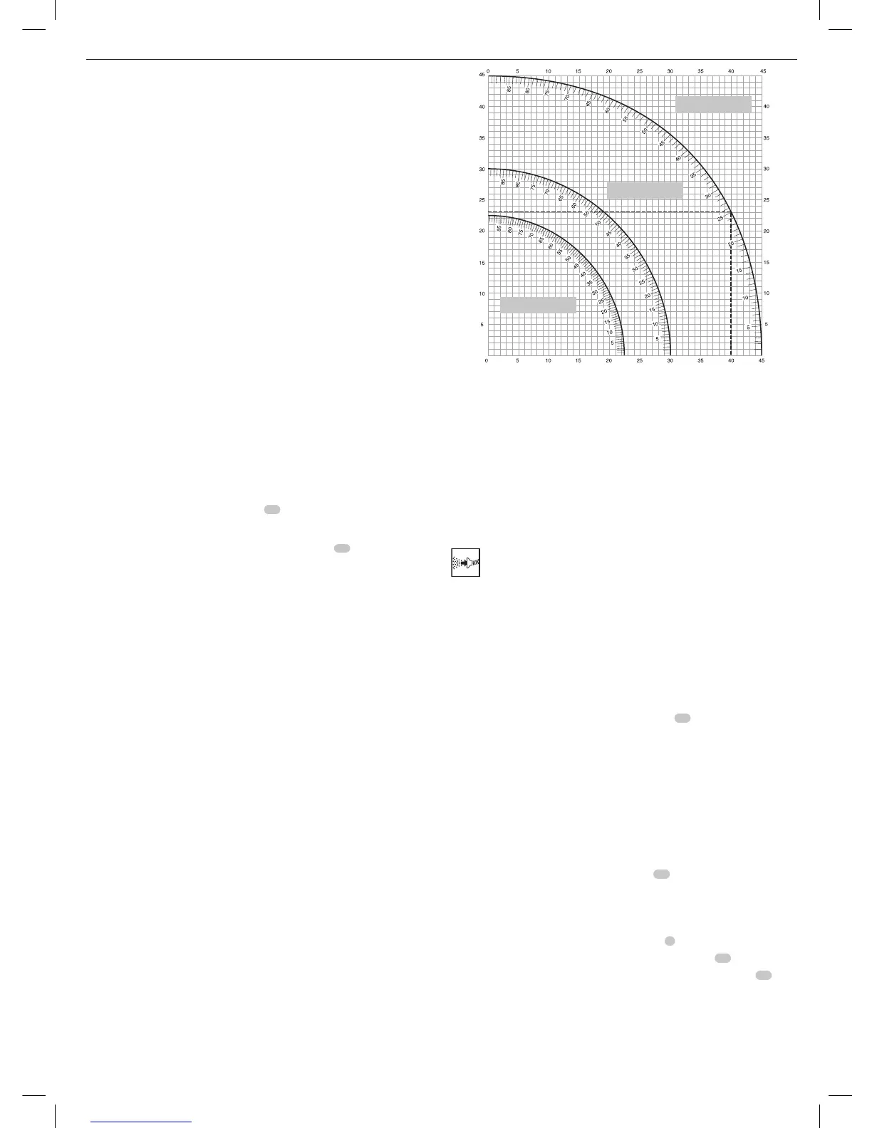
• The chart shown below will assist you in selecting the proper bevel and
mitre settings for common compound mitrecuts.
• To use the chart, select the desired angle “A” (Fig.S) of your project
and locate that angle on the appropriate arc in the chart. From that
point follow the chart straight down to find the correct bevel angle and
straight across to find the correct mitreangle.
Set this miter angle on saw
Angle of side of box (angle ”A”)
Set this bevel angle on saw
1. Set your saw to the prescribed angles and make a few trialcuts.
2. Practice fitting the cut piecestogether.
Example: To make a four-sided box with 25° exterior angles (angle “A”)
(Fig.S), use the upper right arc. Find 25° on the arc scale. Follow the
horizontal intersecting line to either side to get the mitre angle setting
on the saw (23°). Likewise follow the vertical intersecting line to the top
or bottom to get the bevel angle setting on the saw (40°). Always try
cuts on a few scrap pieces of wood to verify the settings on thesaw.
WARNING: Never exceed the compound mitre limits of 45° bevel with
45° left or rightmitre.
Dust Extraction (Fig. A, G)
WARNING: Whenever possible, connect a dust extraction device
designed in accordance with the relevant regulations regarding
dustemission.
Connect a dust collection device designed in accordance with the relevant
regulations. The air velocity of externally connected systems shall be 20m/s
+/- 2 m/s. Velocity to be measured in the connection tube at the point of
connection, with the tool connected but notrunning.
NOTE: The DWV9000 twist-lock quick connector
48
is recommended as an
optional accessory to connect to the dust extractiondevice.
Observe the relevant regulations in your country for the materials to
beworked.
The vacuum cleaner must be suitable for the material beingworked.
When vacuuming dry dust that is especially detrimental to health or
carcinogenic, use a special vacuumcleaner.
Transporting (Fig. A, B)
WARNING: In order to conveniently carry the mitre saw, the base is
provided with two hand indentations
31
. Never use guards to lift or
transport the mitresaw.
1. To transport the saw, set the bevel and mitre positions to 0°.
2. Push the saw head all the wayback.
3. Press the lower guard lock up release lever
2
(Fig.A).
4. Press the head down and press the lock down button
22
(Fig.B).
5. Bring the saw blade to rest position and press the traverse lock
18
.
8 SIDED BOX
6 SIDED BOX
SQUARE BOX
 Loading...