8514-219-001 REV E PAGE 9
4. ELECTRICAL REQUIREMENTS:
The electrical installation must be performed by a qualified electrical technician.
The electrical power requirements necessary to operate the unit satisfactorily are listed on
the serial plate located on the back panel of each dryer. The electrical connection should be
made at the terminal blocks in the control box on the rear of the unit using conductors rated
at 75 C (167 F) and a wire size adequate to handle the amperage and voltage listed on the
serial plate (see table below for recommended minimum sizes). It is absolutely necessary that
the dryer be connected to a known earth (No. 8 AWG copper conductor recommended).
Knockouts are provided for the connection of 1-inch (25 mm) conduit for the power supply
conductors and 3/8-inch (10 mm) conduit for the external earthing conductor. It is absolutely
necessary that the dryer be connected to a good earth connection. The earth connection
resistance should be checked prior to operation. Introduction of supply wiring must not
increase the Ingress Protection (IP) rating.
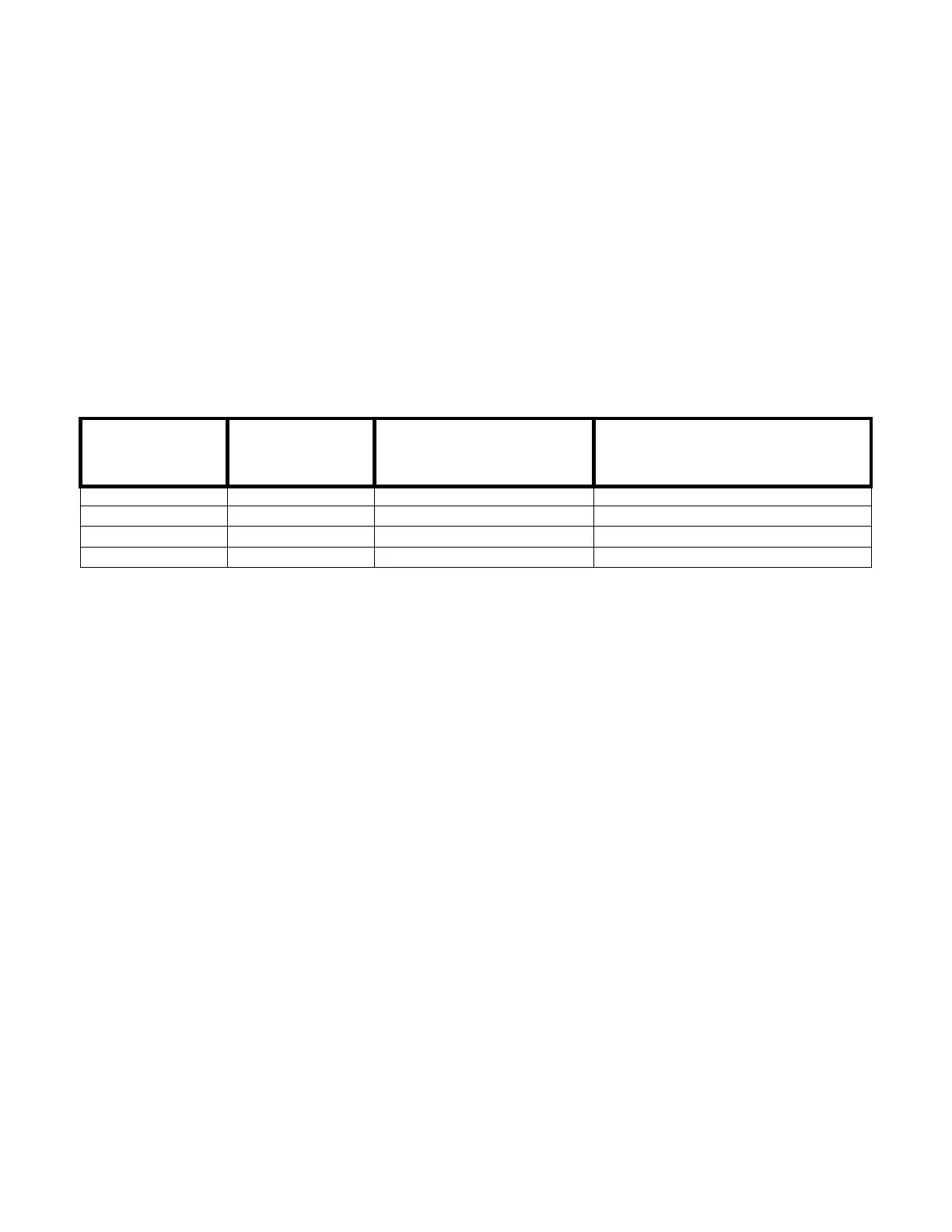
HEATING ELEMENT
SIZE (kW)
SUPPLY VOLTAGE
(
PHASE / V.)
MINIMUM DUAL ELEMENT
TIME DELAY FUSE SIZE AT
FUSED DISCONNECT (A.)
MINIMUM WIRE SIZE FROM FUSED
DISCONNECT TO DRYER TERMINAL
BLOCK (75
O
C COPPER WIRE)
22 3
400 50 # 6
13.3 mm^2
24 3 / 415 50 # 6 (13.3 mm^2)
30 3 / 400 60 # 4 (21.1 mm^2)
36 3 / 400 80 # 3 (26.7 mm^2)
The installation must meet the electrical requirements of the country, state, or locality of
installation. The installer must provide a disconnect switch, which will interrupt all lines. It
may be a local or national requirement to provide an electrical interruption switch visible and
accessible from the room in which the dryer is installed. The wiring diagram is located in the
belt guard on the back of the dryer.
For destination countries where CE requirements must be met, individual 400V supply
disconnecting devices for each dryer are required and must be one of the following types:
a. switch-disconnector with fuses per IEC 60947-3 utilization category AC-23B;
b. disconnector with fuses per IEC 60947-3 having an auxiliary contact that in all cases causes
switching devices to break the load circuit before the opening of the main contacts of the
disconnector;
c. a circuit-breaker suitable for isolation per IEC 60947-2;
d. any other switching device in accordance with an IEC product standard for that device and
which meets the isolation requirements of IEC 60947-1 as well as a utilization category defined
in the product standard as appropriate for on-load switching of motors or other inductive loads;
The supply disconnecting devices must
a. provide a means allowing the supply disconnecting devices to be locked in the OFF position;
b. be mounted 0.7 m to 1.7 m above the floor, within 2 m from the dryer, and within 8 m from
the operator position;
c. have a red actuator to indicate that it serves a dual Emergency Stop function;
d. be rated for branch circuit operation;
e. be approved for use in the country where installed;
 Loading...