Chapter 3 - Hardware Installation
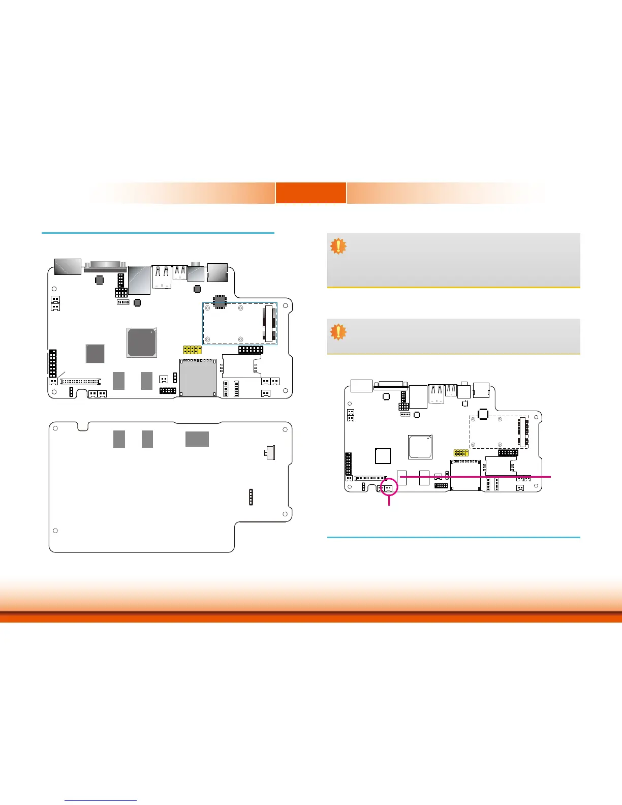
Board Layout
1
ON
23456
SW4
1
10
3
COM1
debug
port
1
109
2
Power LED
Chassis Intrusion
Freescale
i.MX535
DDR3
1
Clear CMOS
(JP1)
RTC_Battery
DDR3
1
39
LVDS
2
40
1
AMP_R
VGA
1
15
2
16
Reset
Power Button
JTAG
1
2
11
12
SW28
SW29
456 1
ON
2378
456 1
ON
2378
3G LED
MIC
AMP_L
SIM
1
13
14
2
DIO
USB 6-7
3G_Modem
1
2
9
10
HDMI Chip
Sil9022
Audio Chip
SGTL5000
LAN Chip
SMSC 8710
Panel Power
Select
(J11)
UART 2 Chip
SP338
PMIC
DA9053
COM2 RS232/422/485
HW/SW Mode Select(JP7)
1
1
2
2
12
1
1
1
+ -
MMC/SD
HDMI
Line-out
Mini USB
LAN
USB 4-5
COM2
DC-in
System Memory
DDR3
Important:
Electrostatic discharge (ESD) can damage your board, processor, disk drives, add-in
boards, and other components. Perform installation procedures at an ESD workstation
only. If such a station is not available, you can provide some ESD protection by wear-
ing an antistatic wrist strap and attaching it to a metal part of the system chassis. If
a wrist strap is unavailable, establish and maintain contact with the system chassis
throughout any procedures requiring ESD protection.
Important:
When the Standby Power LED lit red, it indicates that there is power on the system
board. Power-off the PC then unplug the power cord prior to installing any devices.
Failure to do so will cause severe damage to the motherboard and components.
•DDR3onboard
•Onboardmemory
- 1GB: standard
- 2GB: optional
Power LED
Features
DDR3
DDR3
eMMC
Touch
Screen
5
1
Android Hot Key Connector
Top View
Bottom View