www.dfi .com
9
Chapter 1 Introduction
Getting to Know the KS211/212
Chapter 1
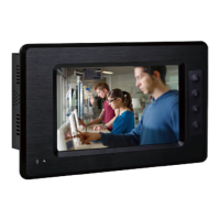
Front View
Power LED
Indicates the power status of the system.
Function Keys (KS211)
Used to navigate through the pages.
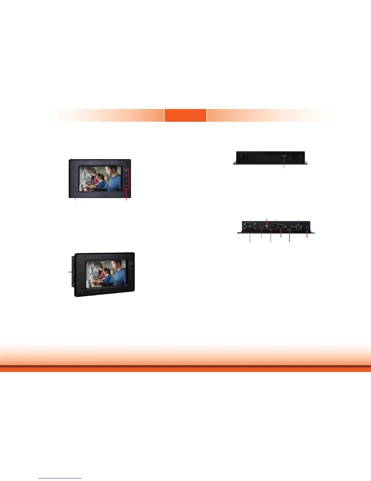
Top View
SD/MMC
Indicates to insert and SD and MMC.
Bottom View
COM
Used to connect a serial device.
Mini USB
Used to connect a Mini USB device (only as client).
USB
Used to connect USB 2.0/1.1 devices.
LAN
Used to connect the system to a local area network.
GPIO
Supports 6-bit input and 6-bit output GPIO connector (with power).
Line-out
Used to connect to a speaker.
DC-in
Used to plug a power adapter.
Power Switch
Press to power-on or power-off the system.
HDMI
Used to connect an HDMI device.
Power LED Function Keys
SD/MMC
2W built-in speaker
Side View
Speaker
Bult-in with 2W speaker in the right and left sides.
Power Switch
Line-out
USB 9-30V DC-in
HDMI
RS232/422/485 COM
12-bit GPIO
Mini USB
LAN