PROLYTE ANALYZER
13
2.c DC Power Verification
1. Remove the rear housing. See Rear Housing Removal in the REPAIR SECTION for
details.
2. Connect the power cord first to an outlet, then to the entry module.
3. Connect the reference side of the voltage meter to TP12 on the CPU board.
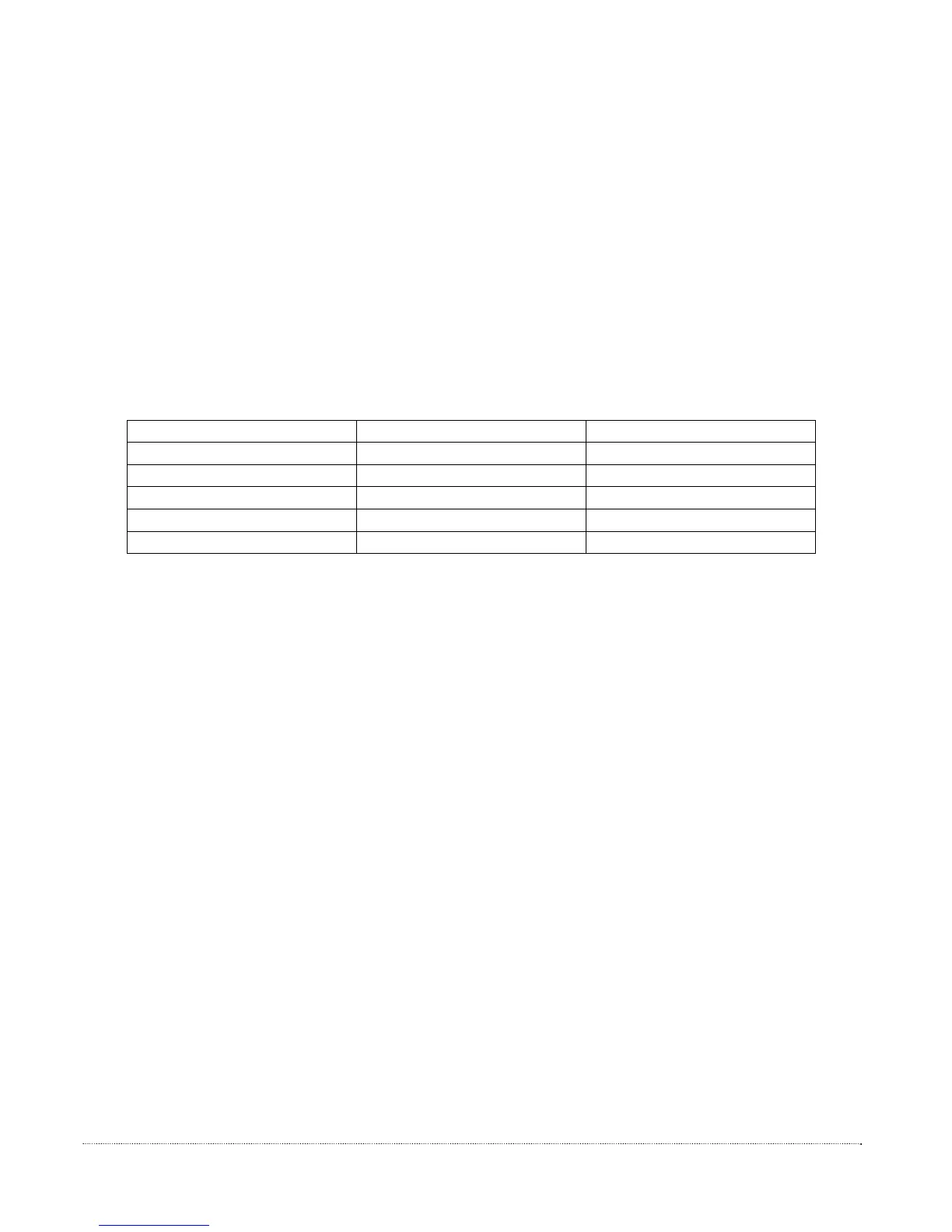
4. Verify the voltage at each test point listed below.
Test Point Value Tolerance
TP1 5.00 V +/- 0.15 V
TP2 36.0 V +/- 2.0 V
TP3 5.00 V +/- 0.15 V
TP10 2.50 V +/- 0.10 V
TP11 -5.00 V +/- 0.15 V
5. If any of the voltage values in STEP 4 are not within specification, AND the AC
power verification is successful, replace the CPU board.
2.d Display Verification
1. Disconnect the display cable from the CPU board. See Display Assembly Removal in the
REPAIR SECTION for details.
2. Connect a known good display assembly to the CPU board and connect the main
power cord. Verify that the test display is operative. Based on the test results, take the
appropriate corrective action.
-Display Blank and/or YES/NO buttons DO NOT operate:
Remove the test display cable. Perform AC and DC power
verification. If the AC and DC power tests are successful, replace the
CPU board with a new CPU board, and return to normal operation.
See CPU Board Removal in the REPAIR SECTION for details.
-Display On and YES/NO buttons function:
Remove the original display assembly and replace with a
new display assembly.
See Display Assembly in the REPAIR SECTION for details.