5
Securely attach the part specimen to the table substrate using whatever method is appropriate for
the material.
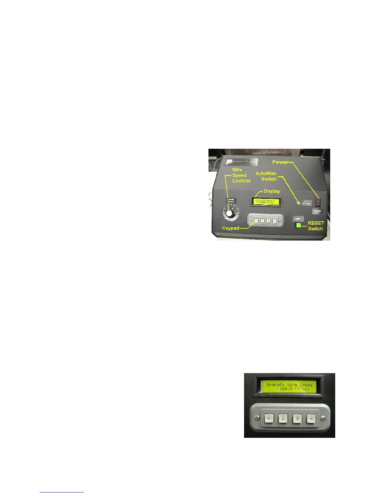
Operator Interface
This section describes the controller’s user interface, including each of the input switches and the
LCD display.
POWER rocker switch – Provides AC power to the
controller and the saw.
AUTO/MANUAL switch – Manual mode allows
manual jogging of the saws functions and is used to
perform the bow sensor calibration. Use Automatic
mode to program, store, and initiate an automatic cut
program.
RESET pushbutton with built in indicator light –
In Manual mode, this toggles operation of the wire
drive. In Automatic mode, this begins an automatic
cut program once you have been prompted through the necessary setup screens.
Controller Box
WIRE SPEED control – Controls the speed of the cutting wire. Typically, you will turn the wire
Speed control to near 20% to before motion begins. This is the minimal motor drive current
necessary to overcome initial stiction.
LCD display – the 20 character by 2 line alphanumeric display provides a means of prompting the
operator for necessary programming and operational information, as well as status information
during automatic operation.
Keypad – The function of the four arrow keys will vary slightly depending on the action that is
being prompted for on the display. Exceptions will be noted in each of the screen descriptions, but
in general, they behave as follows:
Left Arrow – Go back to the previous screen.
Down Arrow – Jog an axis, scroll down through the
available choices, or decrease a numeric value.
Up Arrow - Jog an axis, scroll up through the available
choices, or increase a numeric value.