24
Use the up and down arrow keys to specify the cutting gap, or distance between the inside edges of
the two guide pulleys. When ready, press the right arrow key to proceed.
At this screen you are being asked to confirm that the wire is straight between the guide pulleys.
This is also the opportunity for final preparations before motion and calibration begins in the next
step.
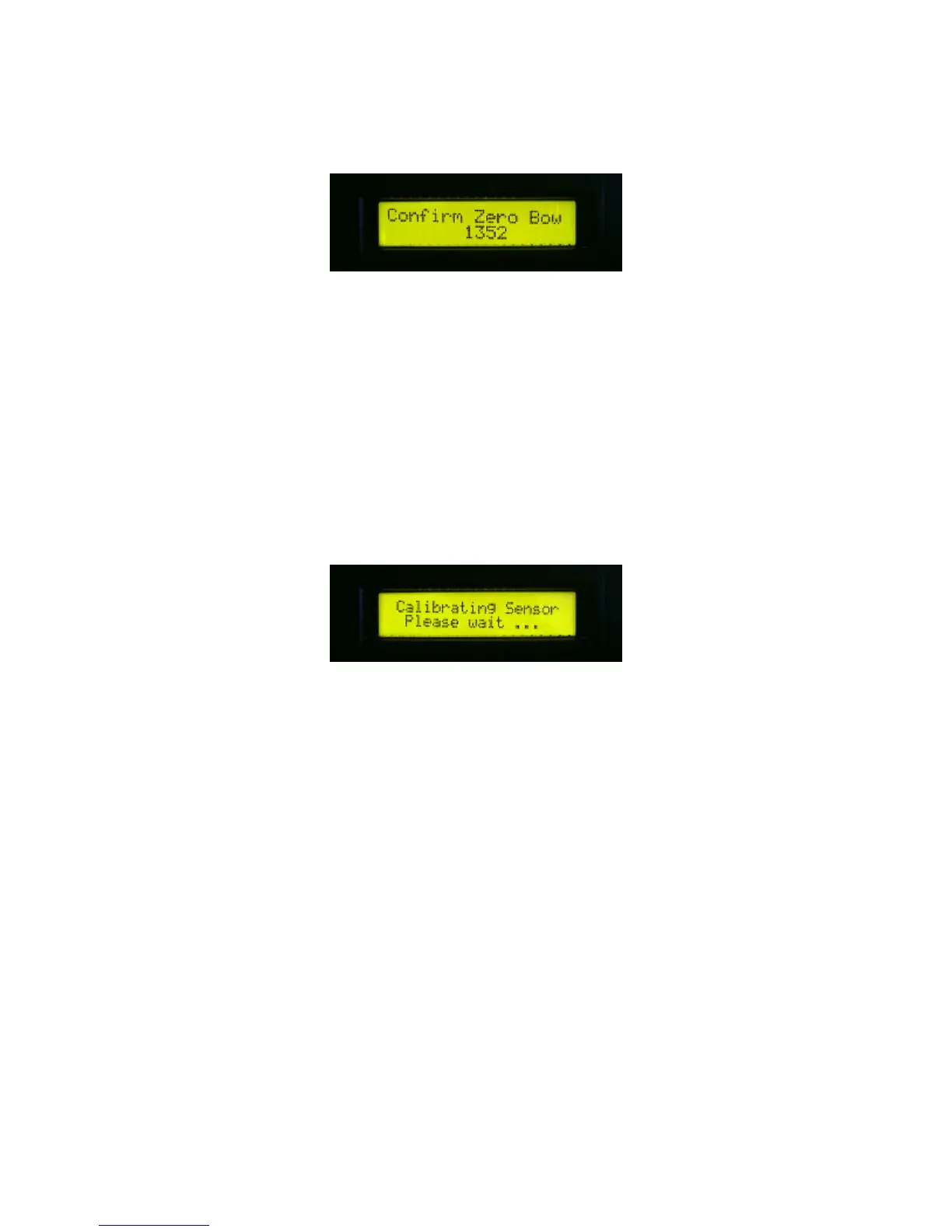
Using your finger, gently bow the wire up so that it passes the sensor face. Notice the sensor
reading change from between 800 - 1100 for no bow, to about 1800 for maximum bow when the
wire passes up from the center of the circular sensor face. Pressing the wire down slightly toward
the centerline of the sensor should result in a 50 - 100 point drop in the zero bow value. (This is
required for proper calibration.)
Press the right arrow key to proceed. Beware that up to one inch of downward motion is about to
occur. Ensure that nothing will interfere with this motion.
The yoke makes a series of six short downward jogs, storing the sensor readings at each stage.
Then, the yoke rises to its original position. When calibration is complete, the next typical step is to
jog the wire up, if necessary, to clear the calibration block. Remove the block or wedge. This
completes the calibration procedure.
Wire Tensioner
One of the more critical factors in obtaining good quality cuts is proper wire tension. Insufficient
tension causes an irregular cut. Too much tension could cause the wire to break prematurely.
Normal operating tension is between 10 and 30psi. Always reduce the pressure to 10psi or less
before flipping the Tensioner RUN/WIRE switch between the RUN and WIRE positions. Use the
following table to set recommended nominal values by wire diameter.