Table of Contents
List of Figures
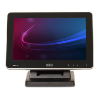
Figure 4-1 Display D2156 ....................................................................................................... 4-1
Figure 5-1 D2156 - Front Panel .............................................................................................. 5-1
Figure 5-2 D2156 - Connector panel ...................................................................................... 5-3
Figure 6-1 GUIDDCMonitorControl......................................................................................... 6-1
Figure 8-1 D2156 - Removing screws .................................................................................... 8-2
Figure 8-2 D2156 - Removing screws .................................................................................... 8-6
Figure 10-1 Waiter Lock kit ....................................................................................................... 10-1
Figure 10-2 Removing Waiter Lock side cover ......................................................................... 10-2
Figure 10-3 Sliding out the side cover ...................................................................................... 10-2
Figure 10-4 Removing the side-attach peripheral connection cover......................................... 10-3
Figure 10-5 Side-attach peripheral connection cover removed ................................................ 10-3
Figure 10-6 Fitting the Waiter Lock into the system.................................................................. 10-4
Figure 10-7 Tightening the Waiter Lock screws........................................................................ 10-4
Figure 10-8 Waiter Lock installed ............................................................................................. 10-4
Figure 10-9 Front view with Waiter Lock................................................................................... 10-5
Figure 10-10 MSR kit .................................................................................................................. 10-6
Figure 10-11 Removing side cover of MSR module ................................................................... 10-7
Figure 10-12 Removing the side-attached peripheral connection cover..................................... 10-7
Figure 10-13 Fitting the MSR module into the system................................................................ 10-7
Figure 10-14 Tightening the screws of the MSR module............................................................ 10-8
Figure 10-15 MSR module installed............................................................................................ 10-8
Figure 10-16 Front view with MSR module................................................................................. 10-8
Figure 10-17 NFC module kit...................................................................................................... 10-9
Figure 10-18 Removing the NFC module side cover.................................................................. 10-9
Figure 10-19 Sliding out the side cover ...................................................................................... 10-10
Figure 10-20 Removing the side-attach peripheral connection cover......................................... 10-10
Figure 10-21 Side-attach peripheral connection cover removed ................................................ 10-11
Figure 10-22 Fitting the NFC module into the ............................................................................ 10-11
Figure 10-23 Tightening the screws of the NFC module ............................................................ 10-12
Figure 10-24 NFC module installed ............................................................................................ 10-12
Figure 10-25 Front view with NFC module ................................................................................. 10-12
Figure 10-26 System overview with BCR ................................................................................... 10-13
Figure 10-27 Front view with BCR .............................................................................................. 10-13
Figure 10-28 Back view with BCR .............................................................................................. 10-14
Figure 10-29 BCR module .......................................................................................................... 10-14
Figure 10-30 Removing the BCR top cover ................................................................................ 10-14
Figure 10-31 Sliding out the BCR top cover ............................................................................... 10-15
Figure 10-32 Removing the peripheral connection cover ........................................................... 10-15
Figure 10-33 Docking the BCR to the system............................................................................. 10-15
Figure 10-34 Swivelling the BCR Scanner.................................................................................. 10-16
Figure 10-35 Tightening the locking screws ............................................................................... 10-16
Confidential External
Copyright © 2023, Diebold Nixdorf
01750368517 B
v
 Loading...