Rev. 1.2 (12.2021) MINI-CUBE | SERVICE MANUAL 44
• CN14: Stepping Motor
• CN15: Home Sensor Optical Switch
• CN12: Reading Sensors LEDS
• CN11: Reading Sensors Leight Detectors
• CN6: USB Ports, to be connected to the Interconnection Board in the Base
block
• CN3: 9Vdc Power Supply + Barcode Reader RS232 Port + RF Antenna output
for the transponder reader. To be connected to the Interconnection Board in
the Base block.
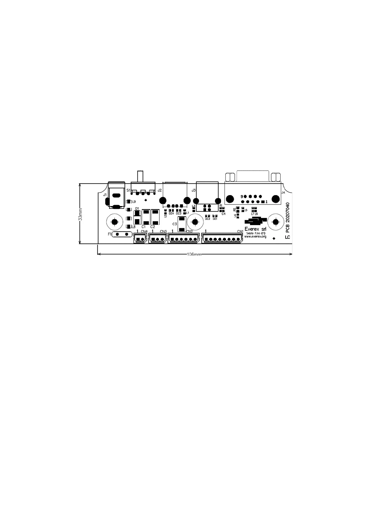
4.1.1 Interconnection board
Figure 31
• J1: 9Vdc / 2A Power Supply Input Jack
• J2: USB HOST port
• J3: USB DEVICE port
• J4: Barcode RS232 port
• CN3: Transponder Antenna
• CN2: USB PORTS input from CPU board
• CN1: POWER Supply out for the CPU Board + RS232 signals for the Barcode
reader and the RF Antenna.