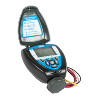
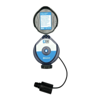
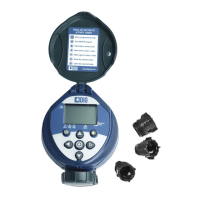
3. system comPonents
To properly install a 710 and 740 series controllers, the
following components are needed:
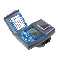
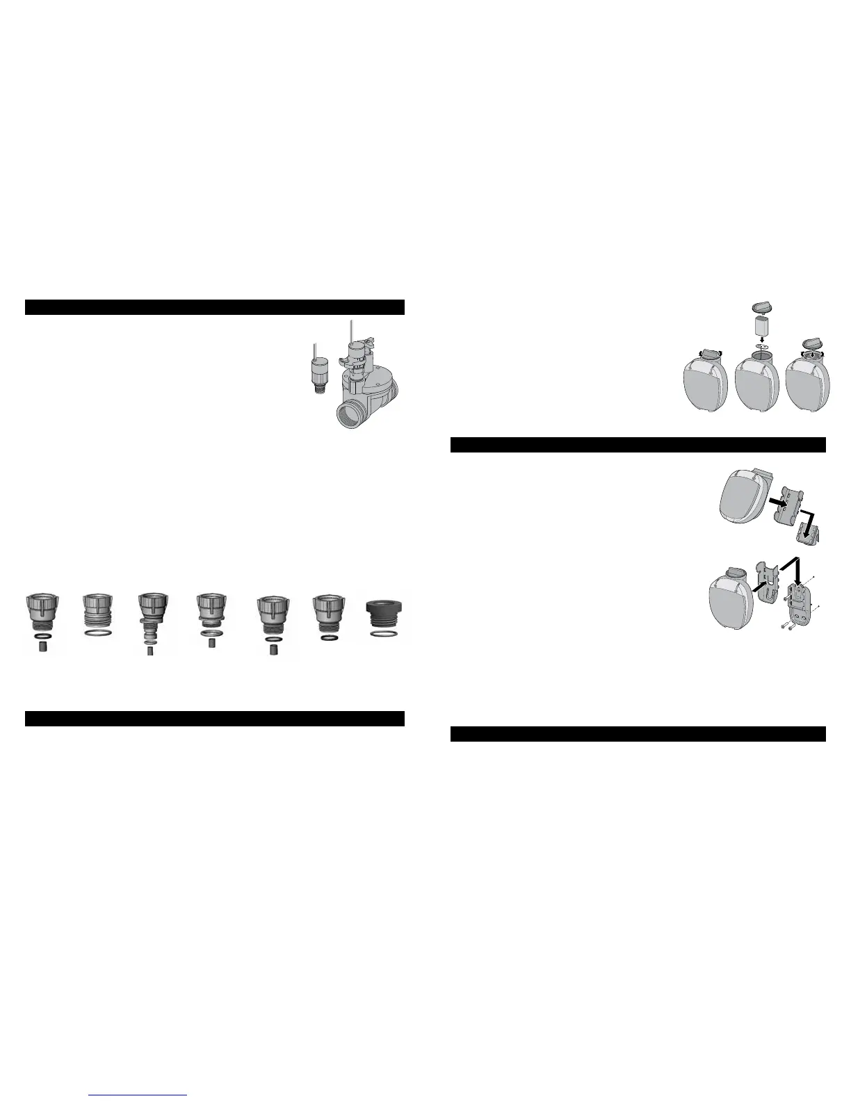
4. battery installation
E1 O-ring
200-014
model #30-494
E2 Short sleeve
model #30-422
E
F1 O-ring
200-014
model #30-494
F
D
D1 O-ring
200-015
model #30-494
D2 Sleeve
model #30-424
C
C1 O-ring
200-012
model #30-495
C2 Long sleeve
model #30-423
B
B1 O-ring
200-021
model #03-077
A
A1 O-ring
200-014
model #30-494
A2 Sleeve
model #30-424
G1 O-ring
200-021
model #30-926
G
IMPORTANT:
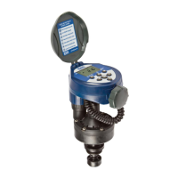
5. ValVes or Wall mountinG
5.1. VALVE MOUNTING
w
q
5.2. WALL MOUNTING
r
e
w
NOTE:
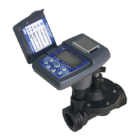
6. installation
6.1. VALVE AND SOLENOID ASSEMBLY
NOTE:
q
w
e
r
 Loading...