22
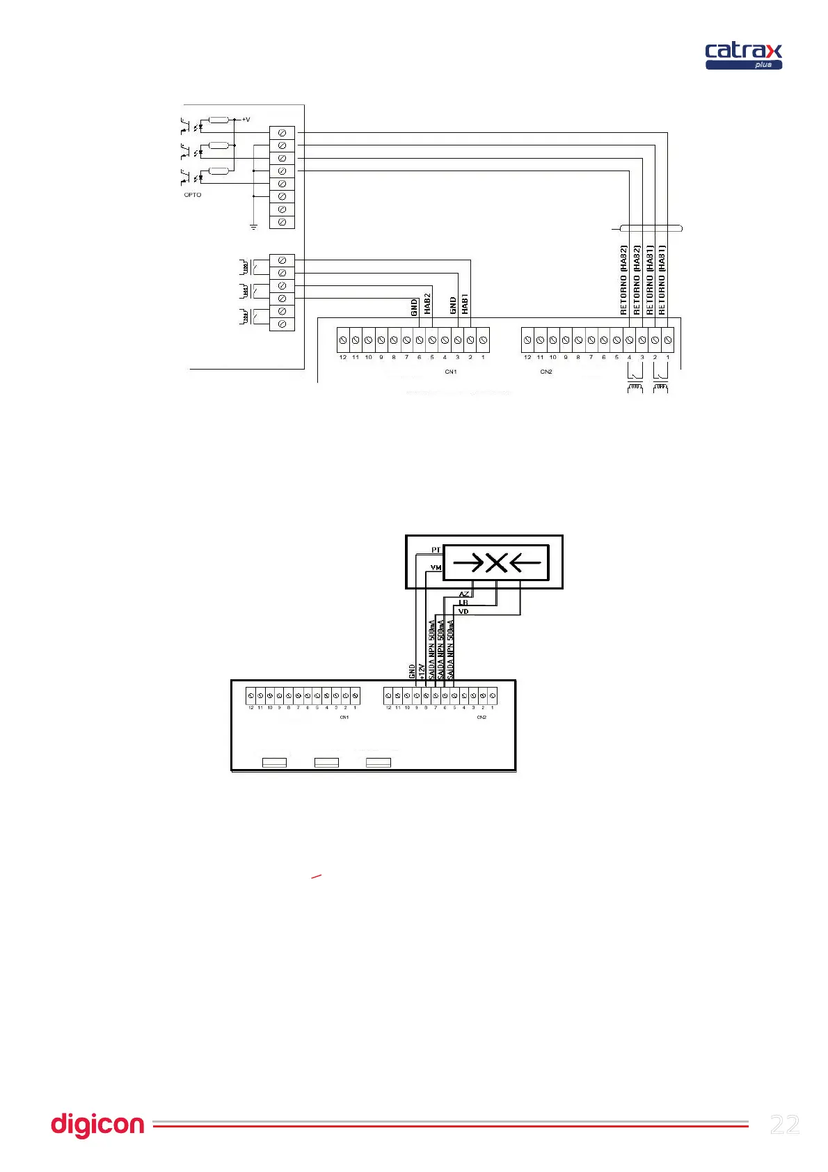
6.4.1.1 Connection scheme
6.4.1.2 Pictogram
The pictogram's outputs are activated by NPN transistors (maximum 500 mA) at the
moment of activation, the GND is sent through a corresponding output.
6.4.1.3
Pictogram connections
6.4.2 Configuration of control board – Switch Ds1
The switch (or dip-switch) DS1 allows programming the following actions:
-passage direction
-Maximum time for turns
-NO inputs (relay or pushbutton contact normally open and without input voltage),
enabling passage in face of these signals; or NC inputs (relay or pushbutton contact
usually closed and with input voltage), enabling passage in the absence of these
signals.
-enabling of a signal for a sound alarm if the access control remains at mid turn for more
than 2 seconds.
To program DS1, put each pin in the desired position, according to the table below:
plus
Return signals
Digicon control board
Inputs
Output
Access control board
Relay
Inputs
Output
Inputs
Output
Digicon control board
Box sensor
Electromagnets
Turnstile
sensors