operation.
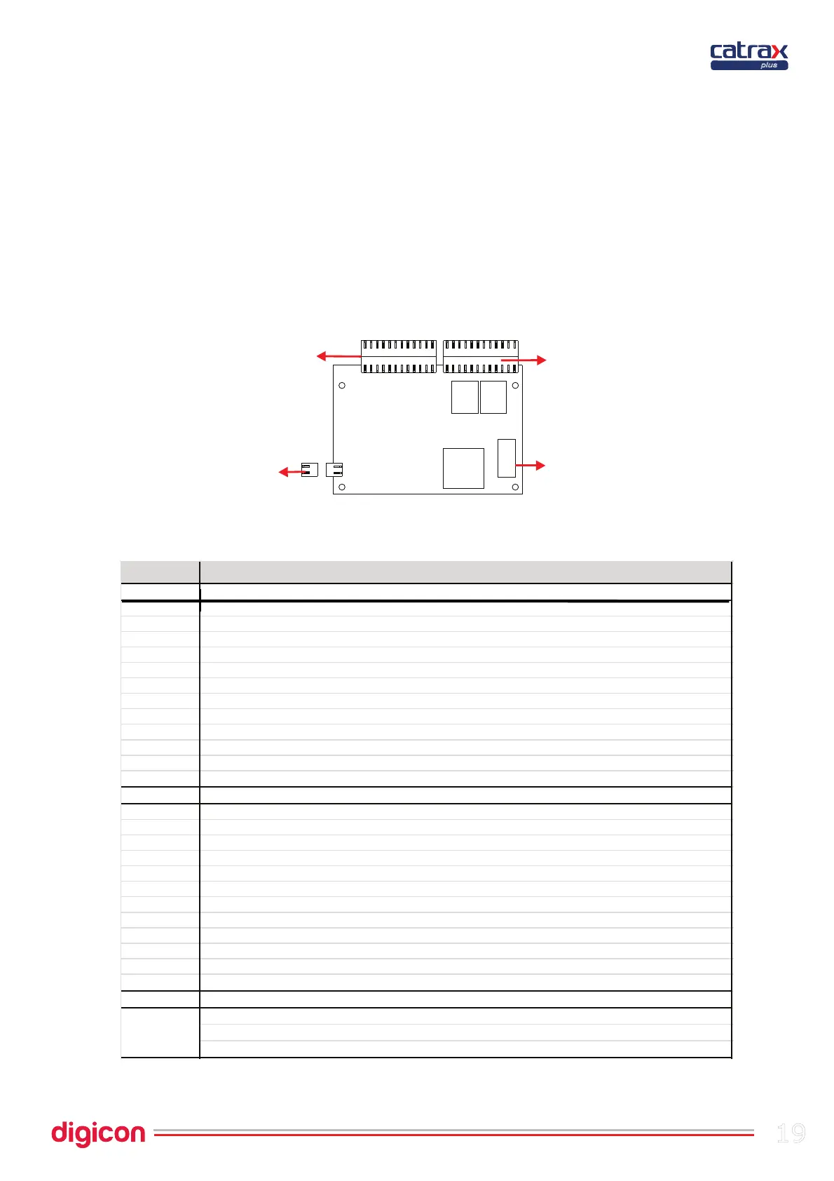
1 (+) vext1 (enables turn through voltage)
2 HAB1 (from right to left)
3 GND
4 Vext2 (enables turn through voltage)
5 HAB2 (enables turn through dry contact – from left to right)
6 GND
7 (+) 12Vcc (available to auxiliary – maximum 500 mA)
8 CLOCK1 (input for reader from left to right)
9 DATA1 (input for reader from left to right)
10 CLOCK2 (input for reader from right to left)
11 DATA2 (input for reader from right to left)
12 GND
CN2 OUTPUTS
1
NO or NC Contact (HAB1 return)
2
Contact C (HAB1 return)
3
NO or NC Contact (HAB2 return)
4
Contact C (HAB2 return)
5
Output for indicative X (open collector NPN – maximum 500 mA) orange w ire Output
6
Output for arrow < (open collector NPN – maximum 500 mA) green w ire
7
for arrow > (open collector NPN – maximum 500 mA) blue w ire
8
(+) 24Vcc (indicative arrows’ pow er) red w ire
9
GND (indicative arrows’ pow er) black wire
10
(+) solenoid of badge collector box
11
(-)solenoid of badge collector box
12 Sound signal (open collector – NPN)
CN3 POWER - POWER INPUT
1 Power input +12Vca
2 Power input GND
3 GND