Chapter 5: Mbox 2 Mini Hardware Overview 31
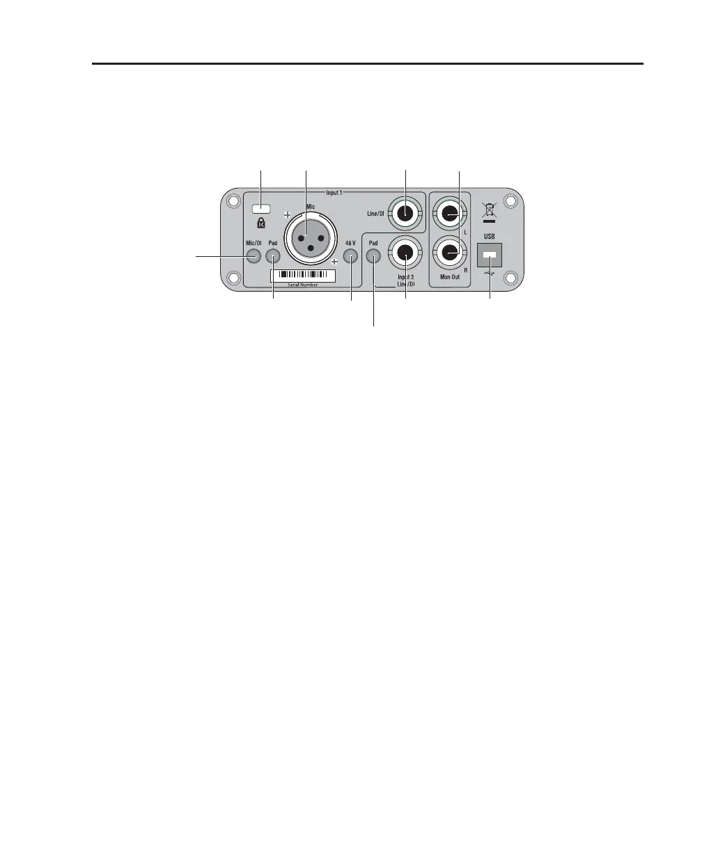
Mbox 2 Mini Back Panel Features
The Mbox 2 Mini back panel has the following features:
Input 1 Section
Mic and Line/DI Inputs
The Input 1 section includes Mic (XLR) and
Line/DI inputs.
The Line/DI input accepts line level signals, in-
struments, and other 1/4-inch TRS (Tip-Ring-
Sleeve) or TS (Tip-Sleeve) connections.
On the front panel, the input signal is adjusted
by the Input 1 Gain control. The source (Mic or
Line/DI) is chosen using the Mic/DI selector on
the back panel.
Mic/DI Switch
This switch selects either the Mic or Line/DI in-
puts for channel 1. When pressed in, the DI in-
put is enabled. When not pressed in, the Mic in-
put is enabled.
Pad Switch
The Pad switch engages a –20 dB pad on the in-
put channel 1. When pressed in, the Pad is en-
abled.
48V Switch
When pressed in, 48V phantom power is active
on the Mic XLR input. Phantom power is pro-
vided for microphones that require it to operate.
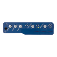
Figure 2. Mbox 2 Mini back panel
Pad
Mic
Mic/DI
Phantom
Power
Line/DI
Input 2
Line/DI
Input 1
Pad
Monitor
Outputs
USB
port
Input
Kensington
Lock port
 Loading...