EasyManuals Logo

DigiPos WD-2030 User Manual

DigiPos WD-2030
48 pages
To Next Page IconTo Next Page
To Previous Page IconTo Previous Page
Page #13 background imageLoading...
Page #13 background image
WD-2030 XXXX customer display
12
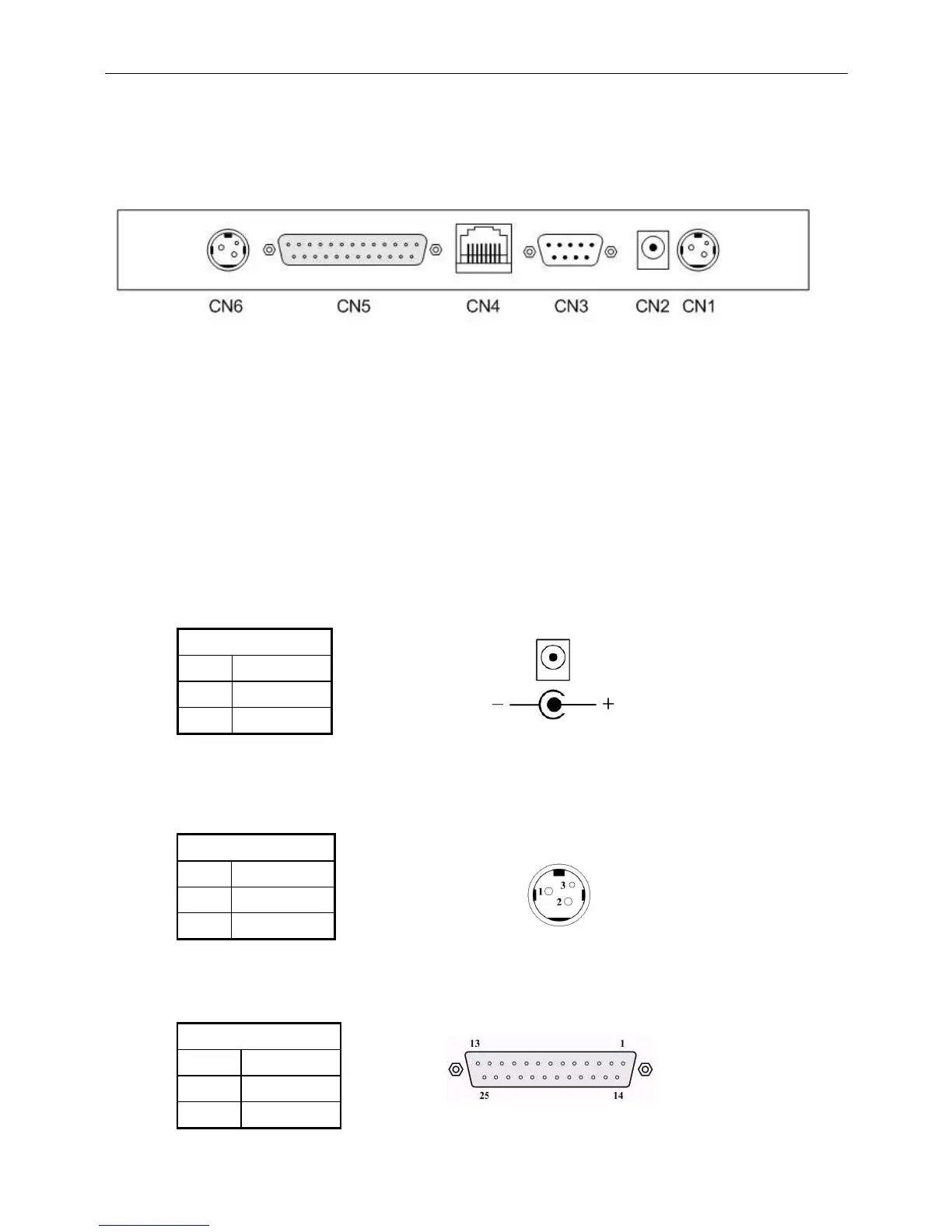
5. Base PCB Interface
5.1 RS-232 Interface connector (On the bottom of the base
section)
CN1,CN6: 24VDC power supply pass-through connects
CN2: Power input connector from adapter
CN3: RS-232C connect to printer
CN4: Connect to display panel
CN5: RS-232C connect to PC/Host
5.2 Power Supply Connectors
The variable power input which are available on base connectors, but only
if one connector can be selected for power input, the description as below:
5.2.1 CN2 / Type: DC jack (5.5/2.1)
Pin assignmen
t
No
Signal
+
Vin1
-
GND
Table 5-1
5.2.2 CN1,CN6 / Type: Miniature jacks quick lock 3 pin
Table 5-2
5.3 CN5 / Type: DB25/F together with signals of RS-232C
Table 5-3
Pin assignmen
t
No
Sig
nal
1
Vin2
2
GND
Pin assignment
No
Signal
16,25
Vin3
7
GND

Table of Contents

Questions and Answers:

Question and Answer IconNeed help?

Do you have a question about the DigiPos WD-2030 and is the answer not in the manual?

DigiPos WD-2030 Specifications

General IconGeneral
BrandDigiPos
ModelWD-2030
CategoryMonitor
LanguageEnglish