860-00186-00 Rev J
Digital Ally Inc.| Device Configuration
IF Box Input Sensors
The Interface Box has six multi-purpose input sensors which must be configured in the DVM for proper
operation. The input sensors can be connected to various devices to trigger an event recording or can
simply be used as a notification in the video information file.
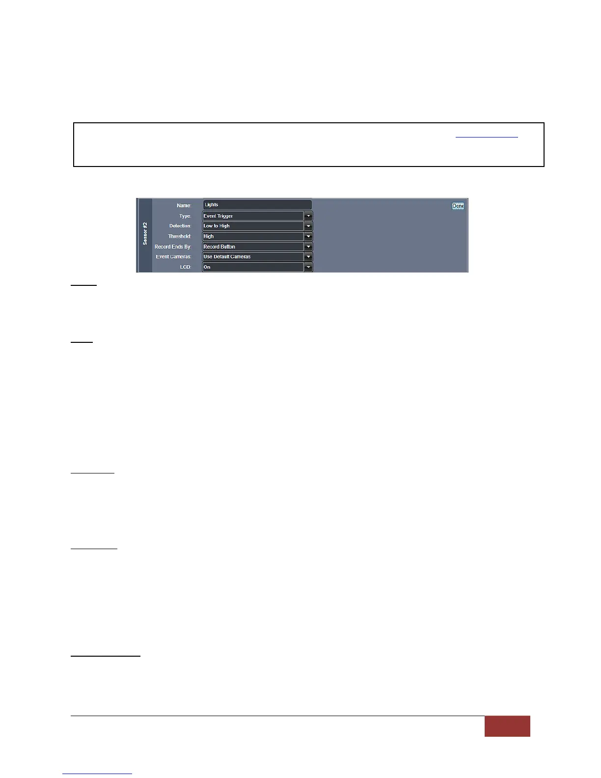
Below are the parameters which must be configured for each attached sensor. Press the Edit button to
make your selections. When you are finished, press Done.
Name
Each input sensor may be given a unique name that will be used to identify the sensor for event
recording, playback and metadata reporting. By default, Sensors 1, 2, 3, and 6 are initially
reserved for the Reverse Gear, Lights, Brakes, and Wireless Microphone respectively.
Type
For each input sensor, select the desired operation. “Event Trigger” will start a DVM record
event, and its data will be logged into the metadata file for that event. “Sensor Only” will not
start a recorded event, but its data will be logged into the metadata file when the DVM is
recording.
“Sensor Only” type sensors follow the Event Priority list (see page 3-18) for camera switching,
LCD control, and output alarm control. Additionally, “Sensor Only” sensors do not extend the
recording time for another event trigger. “Triggered Sensor” is reserved exclusively for the
Wireless Microphone (#6) input sensor.
Settings: Event Trigger, Sensor Only, Triggered Sensor, Disabled [default]
Detection
Select the type of signal that should trigger an event record for the corresponding input sensor.
This setting is the condition of the attached device going from a non-trigger state to the trigger
activated state (Refer to figure 3-17b for more information).
Settings: Low to High [default] – Attached device is triggered by going from low voltage to high voltage.
High to Low – Attached device is triggered by going from high voltage to low voltage.
Threshold
This input sensor threshold setting specifies the level to sense that a trigger has been activated.
When the input sensors are not connected, a voltage level appears on this input which is normal
operation.
The threshold setting of ‘Standard’ or ‘High’ should be determined by using the “Input Sensor
Device Detection, Threshold, and Wiring Guide” chart (Refer to figure 3-17b for more
information).
Settings: Standard [default], High
Record Ends By
For each IF box input sensor, select how the event recording will end when the sensor is the
primary trigger. Choose Sensor to end the recording when the triggered sensor becomes
inactive, or Record Button to end the recording by pressing the Record Button.
Settings: Sensor, Record Button [default]
The first input sensor is generally used for the Reverse Gear signal of the vehicle. Refer to the Backup Camera
section on for details. Sensors 2, 3, and 6 are reserved for the Lights, Brake, and Wireless Microphone. Consult
the DVM-800 Installation Guide for wiring instructions.
 Loading...