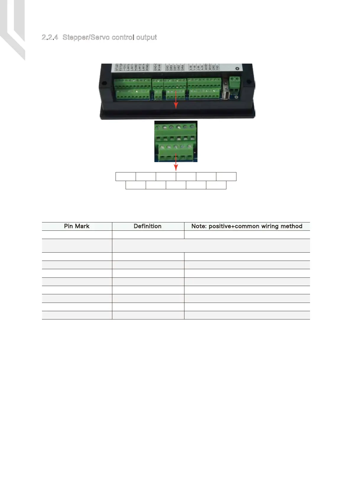
Picture 2-6 shows the stepper/servo control output screw terminals (second group of screw terminals from
the right). As for the connection between system and stepper motor drive, please refer to Table 2-4.
2.2.4 Stepper/Servo control output
Picture 2-6 Stepper/servo control output terminal
GND Dir X Dir Y Dir Z Dir A
+5V-S Step X Step Y Step Z Step A +5V-S
Stepper/servo control interface wiring reference table 2-4
Table 2-4 DDCS V2.1 stepper/servo control interface definition
Pin Mark Definition Note: positive+common wiring method
Note: Strictly avoid to directly connect +5V to GND
+5V-S
Ground
Pulse X -
Direction X-
Pulse Y-
Direction Y-
Pulse Z-
Direction Z-
Pulse A-
Direction A-
5V+ positive terminal
GND
X axis pulse
X axis direction
Y axis pulse
Y axis direction
Z axis pulse
Z axis direction
A axis pulse
A axis direction
Common terminal for Step+ and Dir+
Not used
X axis pulse signal negative terminal
X axis direction signal negative terminal
Y axis pulse signal negative terminal
Y axis direction signal negative terminal
Z axis pulse signal negative terminal
Z axis direction signal negative terminal
A axis pulse signal negative terminal
A axis direction signal negative terminal
Page -9Digtital Dream 4 Axis Motion Controller DDCS V2.1 User’s Manual
 Loading...


