The spindle control output terminal offers connections for Start and Stop of the Spindle (M3/M5),
Start/Stop of Cooling (M8/M9) and Start/Stop of Lubrication (M10/M11). These three output terminals are
signals open to ground. The highest electric current can be absorbed is 50mA. The speed controlling output
terminal can output 0-10V. It can adjust the speed of the spindle motor by sending the voltage between 0 and
10V to the VFD according the the Spindle Speed Setting.
Controlling the speed of a spindle with a VFD (variable frequency drive) only needs the Start/Stop signal
and the 0-10V signal to control the frequency.
M3/M5 is connected to FWD (sometimes called FOD,Forward),
GND-0 is connected to CM (also called DCM),
VSO connects to Speed adjustment which defined by voltage 0-10V,
GND-0 connects to CM (also called ACM).
Many VFD’s have DCM and ACM in common so only one needs to be connected. In case they are not in
common, both need to be connected.
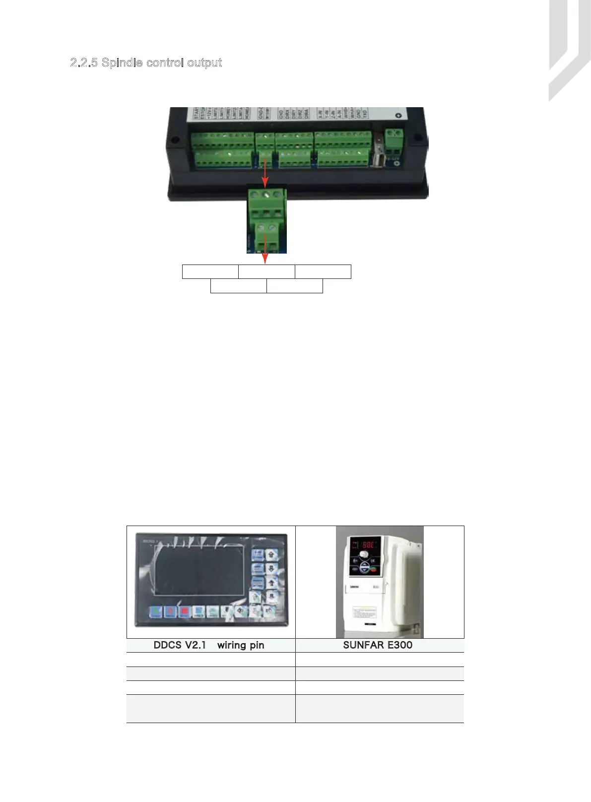
As the picture 2-7 shows, the third group of screw terminal blocks from the right are the spindle control
output terminals. As for the definition, please see Table 2-5.
2.2.5 Spindle control output
Picture 2-7 Spindle control output terminal
VSO M3/M5 M8/M9
M10/M11GND
DDCS V2.1 wiring pin SUNFAR E300
AI
FWD
CM
Speed output(0-10V)VSO
Start and stop of spindle (open ground)
Output ground
Output ground
Note: Some VFD’s have the ground for 0-10V
and the input signal FWD separate. In those
cases both grounds need to be connected.
Table 2-5 DDCS V2.1 VFD wiring
Page -10Digtital Dream 4 Axis Motion Controller DDCS V2.1 User’s Manual
 Loading...


