SYSTEM 3000 to 3505 CONVERSION MANUAL
DIGITIZE, INC. 700254-0001 REV B 02/04
Specifications Subject to Change Without Notice
3-1
3.0 3505 ASSEMBLY
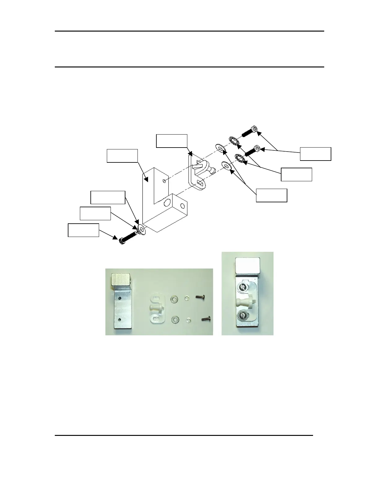
3.1 BRACKET LOCK ASSEMBLY
3.1.1 Attach the Male Cabinet Latch(Item 2) to the Bracket Lock(Item 1) using
Two of each, 4-40x5/16 screws (item 3), #4 flat washer (item 4) and #4
lock washer (item 5). Refer to DWG 1, FIG 1a &1b
DWG 1
FIG 1a FIG 1b
3.1.2 Screw the 6-32x1.128 Socket Head screw (item 6), with one #6 lock
washer (items 9) and one #6 flat washer (item 10), into the Bracket Lock
(Item 1). Slide the assembled bracket lock to the notch on the lower slide
rod (item 8). Lightly tighten Socket Head screw to hold in place.
NOTE: The notch in the rod is placed in the back of the system, so the male stop should
be facing the system’s front. Refer to DWG 1 & FIG 1c
Item #3
Item #5
Item #4
Item #6
Item #9
Item #10
Item #2
Item #1