SYSTEM 3000 to 3505 CONVERSION MANUAL
DIGITIZE, INC. 700254-0001 REV B 02/04
Specifications Subject to Change Without Notice
3-6
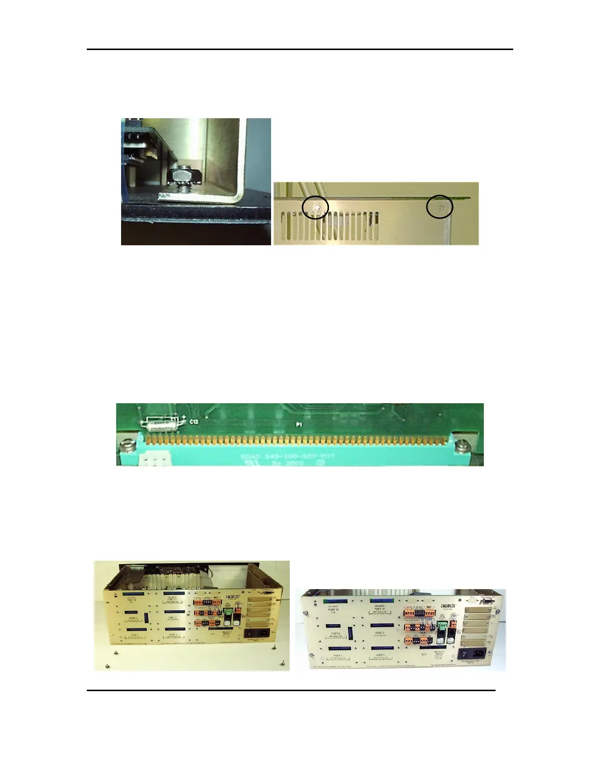
3.4.4 Once the rails are in place, attach the front panel with the 8-32 Kept Nut
on the inside upper right corner of the panel. Use 2, #6 flat head screws to
attach the front panel from beneath the chassis. See FIG 3e & 3f
FIG 3e FIG 3f
3.5 REAR PANEL ASSEMBLY
Install any additional hardware (from step 2.6.1) on the new rear panel.
1. SST Relays and spring clips, K0 and K1.
2. Any 26 pin ribbon cable and hardware, ZONES 1-512, ZONES 513-1024, TCI,
or POINT OUTPUT.
3. If so equipped the AUX PWR OUT cable will not be needed in the 3505.
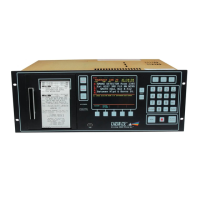
3.5.1 Slide the rear panel into place on the mother board, gently pushing down to
set it snug in the slot. See FIG 4a
FIG 4a
3.5.2 Secure the rear panel to the chassis using 2, #6-32 x 1/2 screw, 2 #6-32 x
5/8 screws, 4 #6 flat washers and 4 #6 lock washers. The 2, #6-32 x 5/8
screws and washers are used, on the right side, with the sliding rails. The 2,
#6-32x1/2 screws and washers are used, on the left side, of the rear panel. See
FIG 4b &4c
FIG 4b FIG 4c