USA
page 42
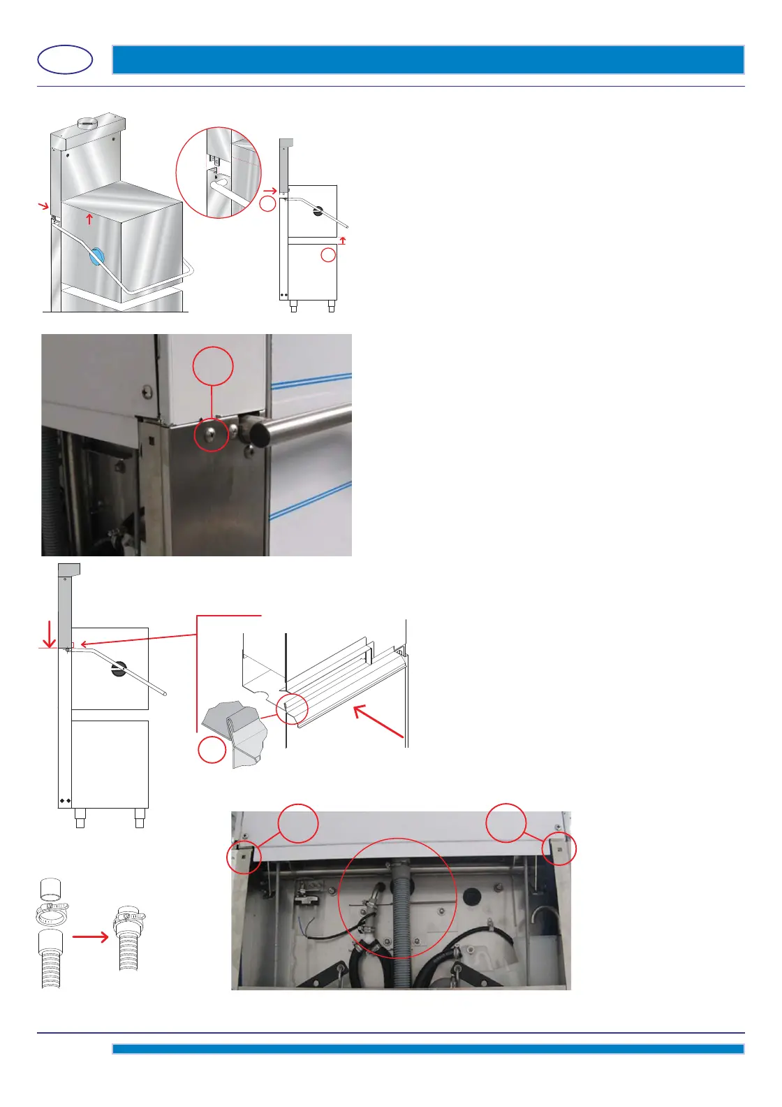
pict. 10
photo 1
1
2
Lift the hood of the machine for about 4 inches (10 cm. - see pict.
10 - detail 1).
Align the Heat Recovery unit above its fi nal seat. (see pict. 10 - detail
2).
Lower the Heat Recovery unit until fi rmly set in its seat (see pict. 10).
B
Fix 2 screws (M6 x 12mm, provided) on the structure side (see
photo 1 - detail B).
Check the right framing of the profi le (see pict. 11 - detail
A).
pict. 11
pict. 12 photo 2
A
Connect the drain hose of the steam condenser, fi rmly tightening by the hose-clamp provided
(see pict. 12 and photo 2).
C
C
 Loading...