USA
page 43
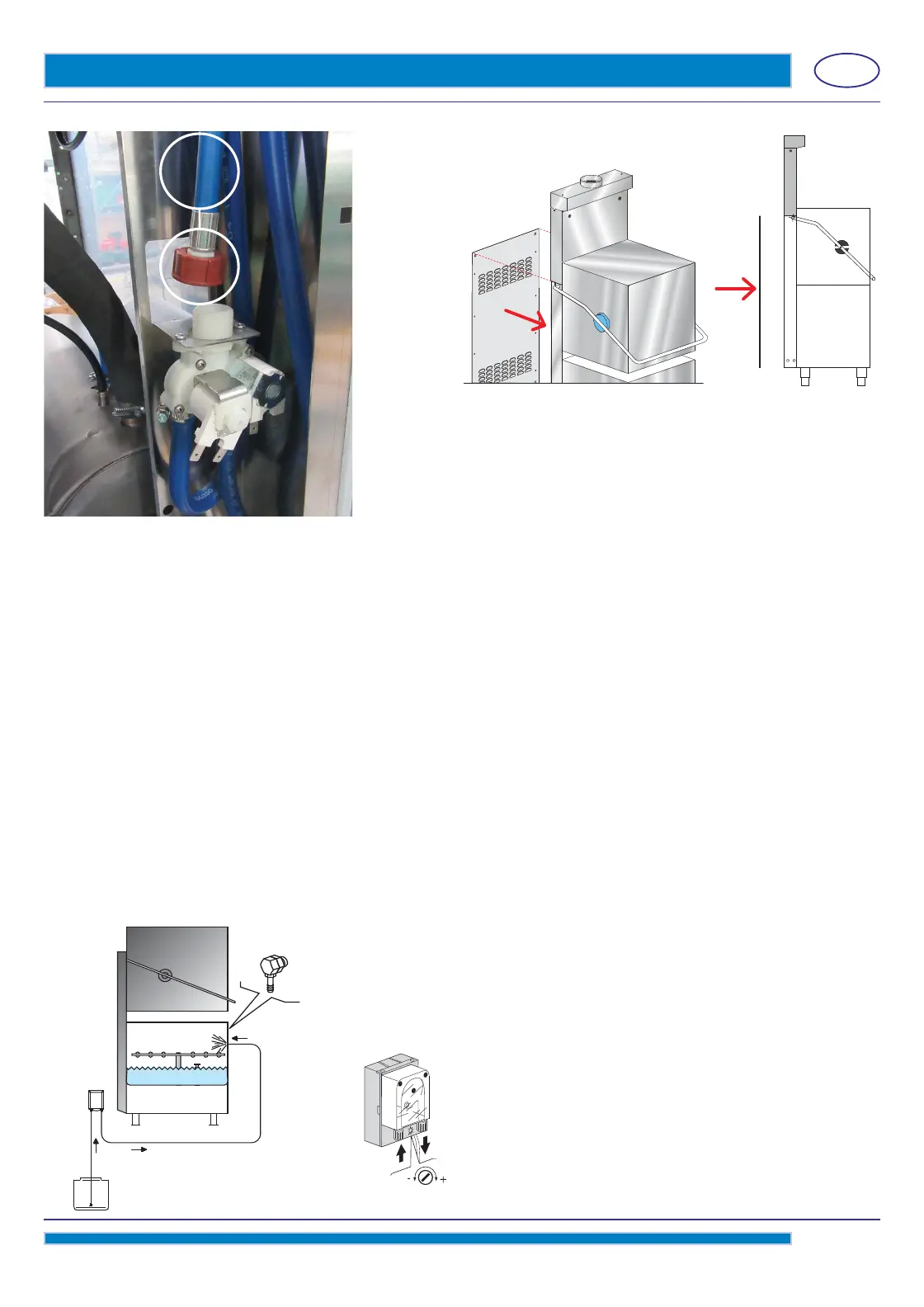
pict. 13
Fasten the ring nut to the solenoid valve (see photo 3 - detail D)
Reassemple the back-panel adding the 2 screws provided (M6 x 12mm)
in the holes (see photo 2 - detail C - see pict. 13)
Fittings provided
4 screws M6 x 12mm (DW11168)
1 hose-clamp 25-40 (DW11806)
photo 3
D
2. DETERGENT DISPENSER RETROFIT
2.1 Electrical connection
Read the electric diagram, enclosed with the machine.
ATTENTION: output arranged for electrical dispenser 230V max 50W.
2.2 Pipe connection
a) A Ø 1/2" (12mm) hole must be made on the back wall of the appliance. On some models the hole has already been made
and is plugged with a plastic cap.
Remove the cap from the hole and fi t the delivery connection.
b) In case a diff erent injector is fi tted, drill a hole of the same diameter as the injector on the back wall of the sump (see pict.
14); this operation must be carried out by the Technical Service.
The hole must be made above the water level.
It's important to make the hole in a far position from the overfl ow pipe, so that the detergent does not fl ow out immediately.
Fix the detergent dispenser in vertical position, with hose connections downwards, making sure not to place it on energized
components. Clean the inside of the machine from any drilling residual.
c) Correctly mount the injector C using the appropriate fi xtures.
d) Connect the suction hose to the suction connection of the dispenser (see pict. 14 point A).
e) Connect the delivery hose to the other connection of the dispenser, and the delivery fi tting (see pict fi g.14 point B).
f) Insert the suction hose with fi lter in the detergent tank.
g) Prime the detergent pump and proceed to dispense.
A
B
C
Point B
pict. 14
CONNECTION DIAGRAM
Point A
pict. 15
 Loading...