MAIN POWER WALL SWITCH WIRING
NOTE:
Wiring of the wall switch must be completed prior to installing the unit.
NOTE:
Use a single pole, single throw wall switch that is rated for 20 amps.
NOTE:
Only install a wall switch on units that do not have a remote control.
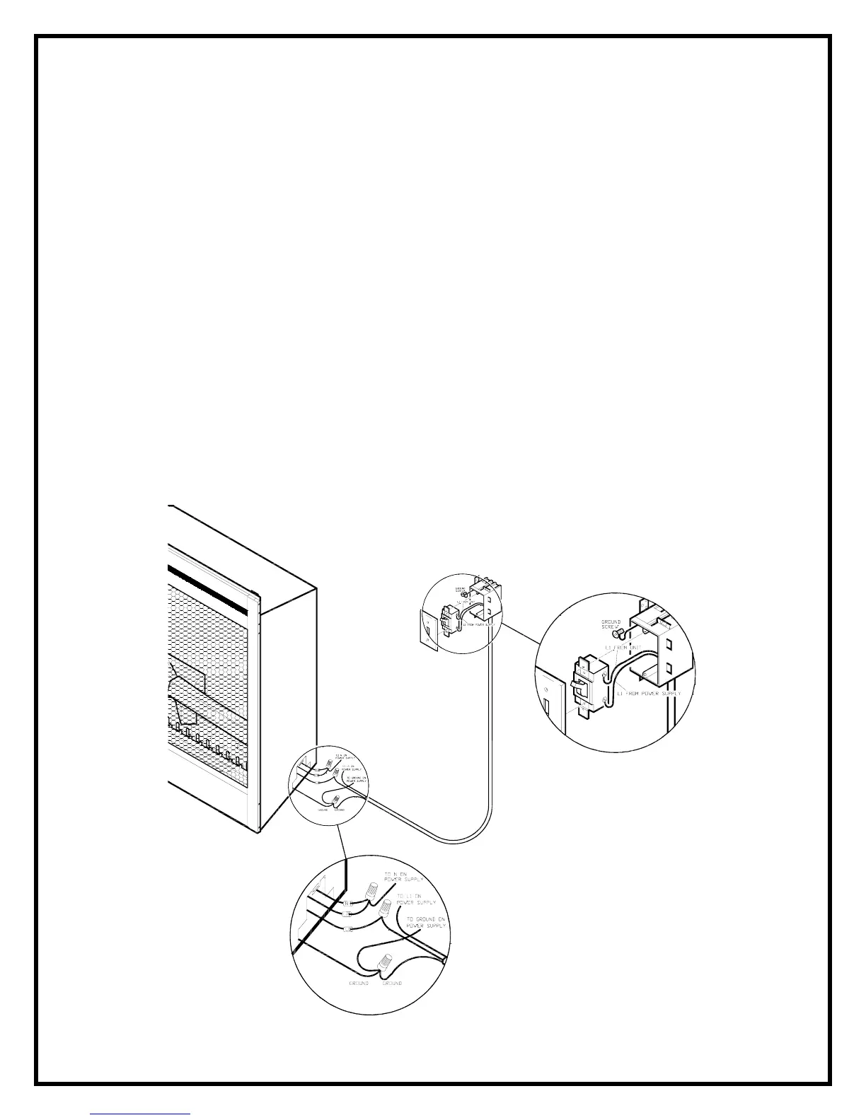
120 VOLT INSTALLATIONS
The wall mounted switch is connected to the fireplace by running a 2 conductor wire with a ground from the junction
box on the back of the unit to the thermostat.
1. Locate the switch on the top corner of the unit.
2. Flip the switch from 230 volt to 115 volt configuration.
3. Loosen the screw securing the junction box cover and remove the cover.
4. Remove the knockouts (if necessary) or use the provided cable clamp.
5. Pull out the four wires marked L1, L2, N, and G.
7. Connect one of the wires from the wall switch to the black L1 wire on the unit, and the other wire to the L1
from the power supply.
8. Connect the red L2 and white N wires to the neutral from the power supply.
8. Connect the ground wire from the wall switch to the ground wire grouping from the power supply.
9. Ensure that all connections are tight. Insert all the wiring into the unit and secure with a cable clamp.