11
ate wire to meet local and national electrical codes for rated
power consumption.
For 240 volt installations a three conductor, non-metallic
sheath cable with ground wire is recommended for the
incoming power supply on replace inserts. Use the appropri-
ate wire to meet local and national electrical codes for rated
power consumption.
REWIRE UNIT FROM 208/240 VOLT TO 120
VOLT WITH REMOTE CONTROLS
!
NOTE: Rewiring the unit from 208/240 volt to 120 volt
conguration must be completed prior to installing the unit.
1. Loosen the screw securing the junction box cover and
remove the cover.
2. Remove the knockouts (if necessary) or use the provided
cable clamp.
3. Pull all of the wiring connections out of the replace junc-
tion box and recongure the labeled wires using the chart
below.
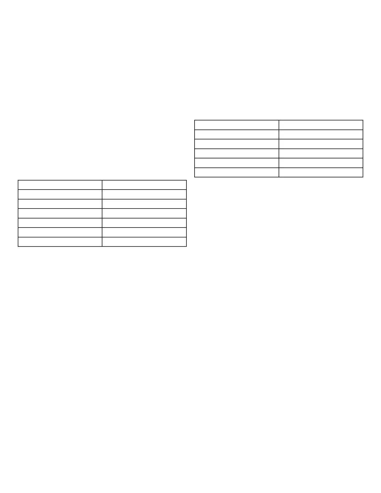
MODELS WITH REMOTE CONTROLS:
208/240V (from factory) 120V
L1, L1, 1 L1, L1, 1
3, 5 F, F, F, 6
L2, 6 7, 8
B, C, 7 B, 3
F, F, F C, 5, L2
8
When the conversion is completed following the above chart
there will be four wires remaining. A red wire that is not used
and must have a wire nut installed, a black (L1) wire, a white
(neutral) wire, and a green (ground) wire.
Connect the black (L1) wire from the unit to the (L1) wire
from the power supply. Connect the white (neutral) wire to
the (neutral) wire from the power supply. Connect the green
(ground) wire to the (ground) wire from the power supply.
4. Once the wiring has been congured for the proper sup-
ply voltage replace wire bundle inside the unit leaving the
connection lines and/or thermostat connections available
for supply power connection.
REWIRE UNIT FROM 208/240 VOLT TO 120
VOLT WITHOUT REMOTE CONTROLS
!
NOTE: Rewiring the unit from 208/240 volt to 120 volt
conguration must be completed prior to installing the unit.
1. Loosen the screw securing the junction box cover and
remove the cover.
2. Remove the knockouts (if necessary) or use the provided
cable clamp.
3. Pull all of the wiring connections out of the replace junc-
tion box and recongure the labeled wires using the chart
below.
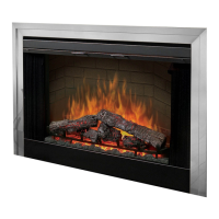
MODELS WITHOUT REMOTE CONTROLS:
208/240V (from factory) 120V
5, 6 2, 3
1, 2 1, 4
3, 4 F, L
2
F 5, 6
L
2
When the conversion is completed following the chart above
there should be two wires remaining. A black (L1) wire and
green (ground) wire. Connect the black (L1) wire from the
unit to the (L1) wire from the power supply. Connect the
green (ground) wire to the (ground) wire from the power sup-
ply. Connect the neutral wire from the power supply to the
wiring connection with wires marked F & L2.
4. Once the wiring has been congured for the proper sup-
ply voltage replace wire bundle inside the unit leaving the
connection lines and/or thermostat connections available
for supply power connection.