10 www.dimplex.com
!
NOTE: A at head screwdriver can be used to gently
pry between the end of the connector and the switch to
release the wires.
8. Replace all of the wiring to their original locations and
reinsert the electronics assembly.
CAUTION: Ensure that the switchboard and terminal
block have not moved from their original locations and all
wires are contained under the cover before reassembly.
9. Re-assemble the remainder of the cassette in reverse
order from the instructions above.
Main Control Board Replacement
Tools Required: Phillips head screwdriver
WARNING: Disconnect power before attempting any
maintenance to reduce the risk of electric shock or
damage to persons.
!
NOTE: Ensure that all of the components that contain
water have been emptied and source water has been
turned o before performing any maintenance.
Primary Side
1. Disconnect and remove the media tray or log set from
the unit and put them in a safe place.
2. Remove the securing screws and metal wire cover at
the end of both of the electronics covers.
3. Remove the 4 screws and both of the electronics cov-
ers from the unit. (Figure 4)
!
NOTE: Use caution when removing the electronics cov-
er, to prevent strain on the connector wire attached to it.
4. Remove the cable clamp, to allow for the assembly to
be lifted out to better access the components.
5. Holding the assembly at either end of the LED light
strip, on the primary end, gently lift the electronics as-
sembly out of the unit (Figure 4).
!
NOTE: There are several wires that run between the
two sides, these wires will need to be gently removed
through the opening on the secondary side to allow the
primary electronics assembly to be lifted out.
6. Locate the main control board.
7. Transfer the wires from the old board to the new board.
!
NOTE: A at head screwdriver can be used to gently
pry between the end of the connector and the switch to
release the wires.
8. Remove the old board from the unit and replace with
the new board.
9. Replace all of the wiring to their original locations and
reinsert the electronics assembly.
CAUTION: Ensure that the switchboard and terminal
block have not moved from their original locations and all
wires are contained under the cover before reassembly.
10. Re-assemble the remainder of the cassette in reverse
order from the instructions above.
Secondary Side
1. Disconnect and remove the media tray or log set from
the unit and put them in a safe place.
2. Remove the 4 screws and the electronics cover from
the unit. (Figure 4)
!
NOTE: Use caution when removing the electronics cov-
er, to prevent strain on the connector wire attached to it.
3. Holding the assembly at either end of the LED light
strip, on the primary end, gently lift the electronics as-
sembly out of the unit (Figure 4).
4. Locate the main control board.
5. Transfer the wires from the old board to the new board.
!
NOTE: A at head screwdriver can be used to gently
pry between the end of the connector and the switch to
release the wires.
6. Remove the old board from the unit and replace with
the new board.
7. Replace all of the wiring to their original locations and
reinsert the electronics assembly.
CAUTION: Ensure that the switchboard and terminal
block have not moved from their original locations and all
wires are contained under the cover before reassembly.
8. Re-assemble the remainder of the cassette in reverse
order from the instructions above.
LED Driver Board Replacement
Will be required when updated MODs B and earlier of the
CDFI-PROs and all MODs of the CDFI-Ps. The new LED
Driver Board is included with new Main Control Boards..
Tools Required: Phillips head screwdriver
WARNING: Disconnect power before attempting any
maintenance to reduce the risk of electric shock or
damage to persons.
!
NOTE: Ensure that all of the components that contain
water have been emptied and source water has been
turned o before performing any maintenance.
1. Follow the steps to access the main board on both
sides of the cassette.
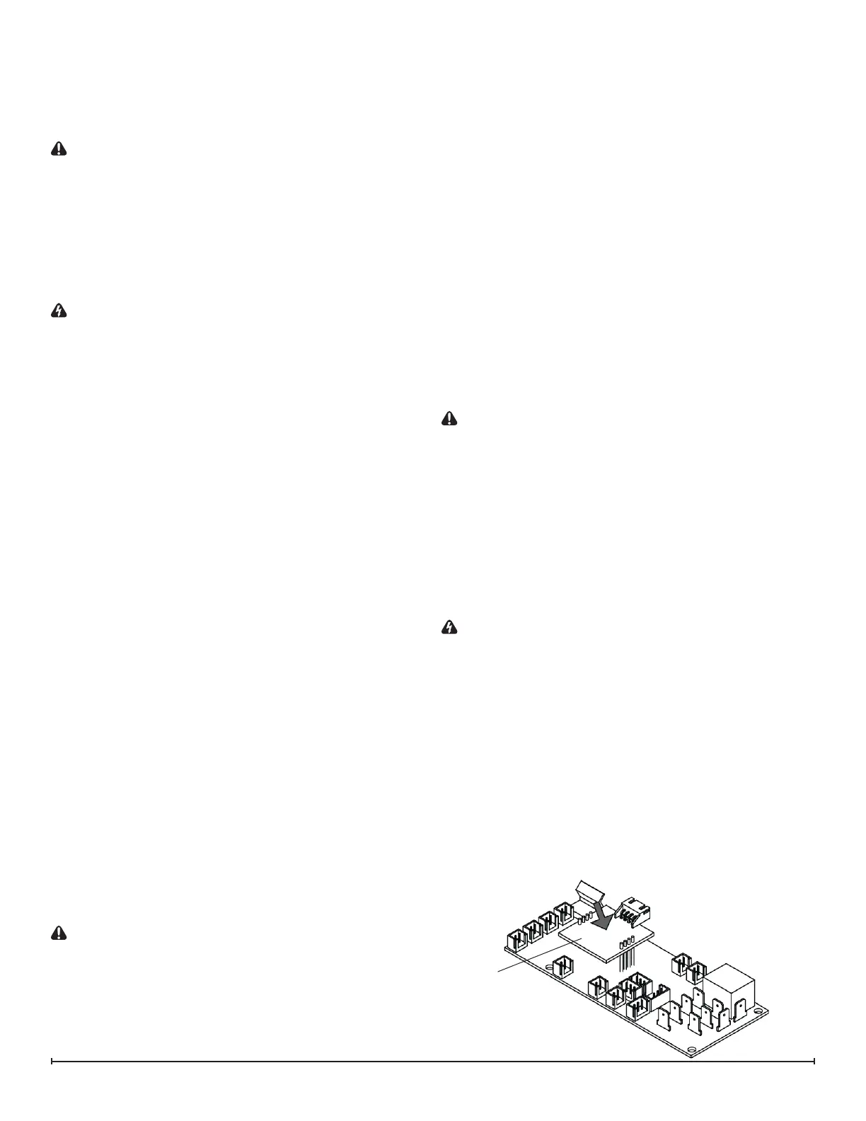
2. Locate and disconnectthe the old LED driver board
(Figure 6)
3. Plug in the new LED driver board.
4. Re-assemble the remainder of the cassette in reverse
order from the instructions given in the “Main Control
Board Replacement” instructions.
Figure 6
LED Driver