6 www.dimplex.com
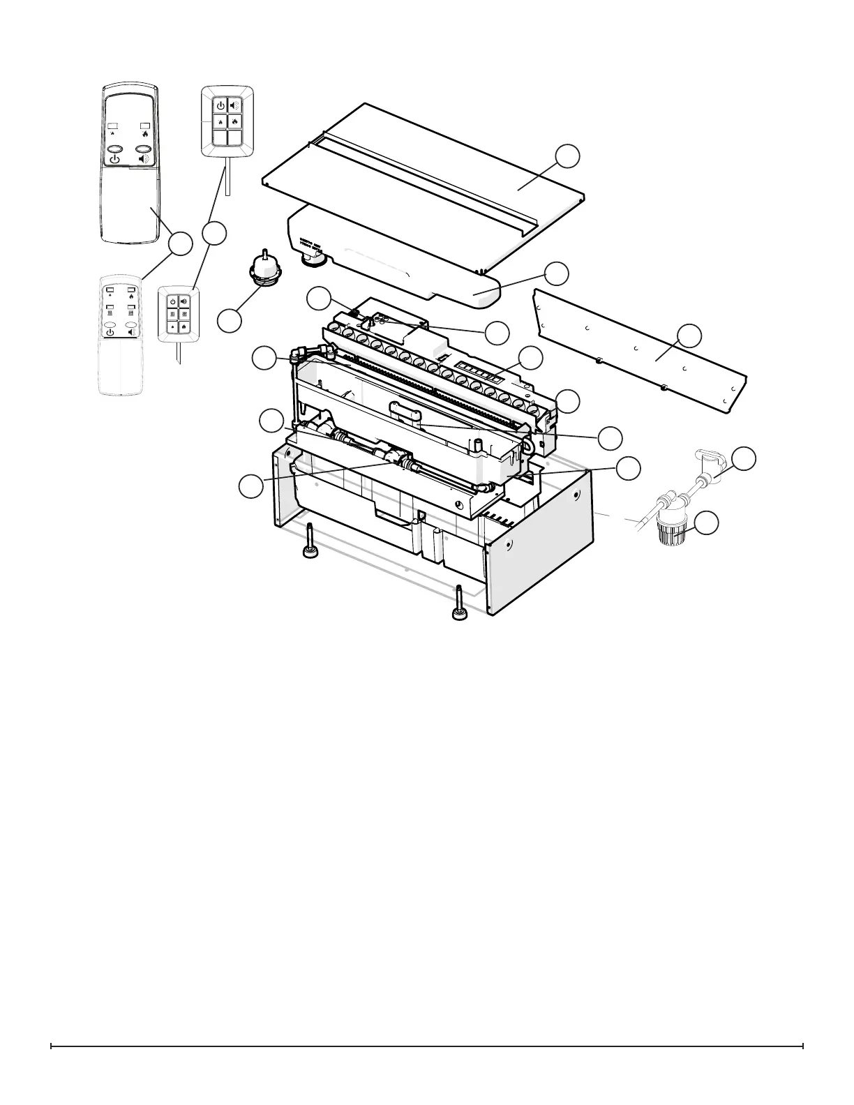
Exploded Parts Diagram - CDFI500
Replacement Parts List - CDFI500P, CDFI500-PROReplacement Parts List - CDFI500P, CDFI500-PRO
1. Main Control Board ................9601270200RP
2. Terminal Block ....................9601260100RP
3. Switch Board .....................9601290100RP
4. Power Supply ....................9601300100RP
5. Fill Cap Assembly .................9601230100RP
6. Heating Element ..................9601240100RP
7. Level Sensor Assembly .............9601320100RP
8. Solenoid Valve ...................9601330100RP
9. Top Cover Assembly ...............9601220100RP
10. Fan Assembly ....................9601310100RP
11. Fan Filter ........................8600300100RP
12. Transducer ......................9601210100RP
13. LED Light Assembly ...............9601250100RP
PRO MOD C (Yellow)* ...........9601250200RP
LED Driver Board ...............9601270300RP
14. Remote Control (1)
CDFI500P .................9601110200RP
CDFI500-PRO ..............9601110300RP
15. Tethered Controller / Receiver (1)
CDFI500P .................9601120200RP
CDFI500-PRO ..............9601120300RP
16. Fused Wire harness ...............9601340100RP
17. Electronic Choke ..................9601380100RP
18. Removable Rell Container with Cap . .9601350100RP
19. Ball Valve .......................9601360100RP
20. Top Plate
CDFI500P .................9601070200RP
CDFI500-PRO ..............9601070400RP
21. Sump ...........................9601200100RP
22. Floats and stopper ................9602550100RP
23. Mesh Filter ......................9601370100RP
24. Red lock clips (package of 5) ........9602490100RP
25. Tether Wire Harness ...............9601080100RP
26. Flame Spacers ...................9601460100RP
2
3
5
7
8
9
13
18
14
15
6
1
20
21
20
A
RELEASE FOR SAMPLING -----
HC
17-05-17
B
ARTWORK UPDATED AS PER DNA -----
HC
06-06-17
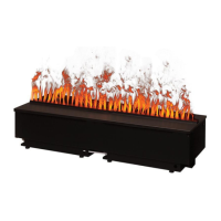
CDFI500-PRO & CDFI1000-PRO
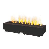
CDFI500P
19
23
*Note that if yellow LEDs are used as replacements for earlier MODs with
original Main Board, new LED Driver Board (9601270300RP) will need to
be installed (included with newer main control boards). All LEDs will need
to be changed for colour consistency.