11
Remove the retaining screws on the top cover and 4.
remove the top, being careful not to damage any of the
wiring.
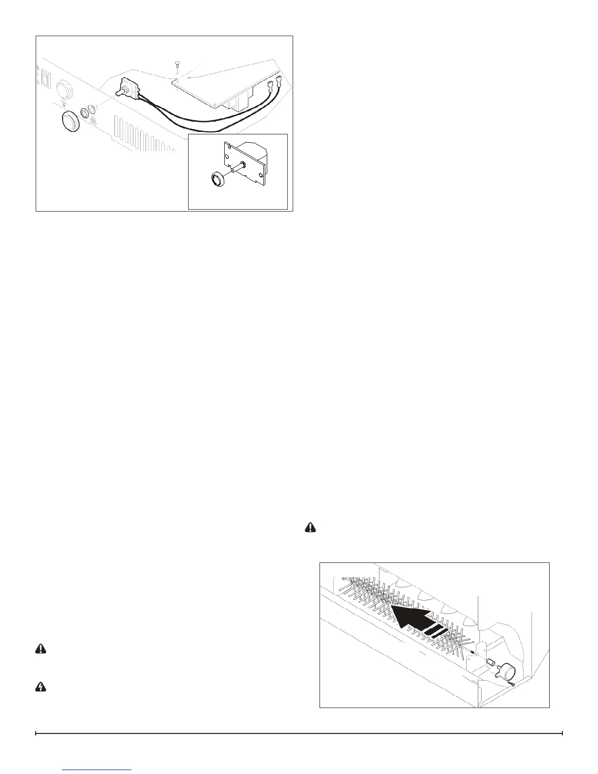
Locate the ame speed control potentiometer and 5.
control board mounted on the top panel (Figure 10)
and disconnect the wires and connections noting their
original locations.
!
NOTE: Using a at head screwdriver, gently pry be-
tween the end of the wires and the potentiometer to release
the wires.
Pull off the control knob from the ame speed control 6.
potentiometer.
Remove either the mounting screws or the retaining nut 7.
and remove the potentiometer.
Properly orient the new ame speed controller and 8.
reconnect all of the wiring connections. (For units made
in Canada proceed to step 11, otherwise continue to
step 9.)
From under the top panel, break off the four mounting 9.
studs on the ame speed control board by grasping
with pliers and twisting on the protruding part of the
stud. Push the remainder of the studs out through the
top panel.
Properly orient and mount the new ame speed control 10.
board, using the new mounting studs, provided, and
reattach all of the wires.
Reassemble in the reverse order.11.
FLICKER MOTOR/FLICKER ROD
REPLACEMENT
Canadian Made Units
Tools Required: Phillips head Screwdriver
Needle Nose Pliers
Flat Head Screwdriver
CAUTION: If the replace was operating prior to ser-
vicing allow at least 5 minutes for light bulbs and heating
element to cool off to avoid accidental burning of skin.
WARNING: Disconnect power before attempting any
maintenance or cleaning to reduce the risk of electric
shock or damage to persons.
Remove the rebox trim by inserting a slotted screw-1.
driver and turning ¼ of a turn to release the trim from
the rebox.
Remove the rebox from the mantel.2.
Gently place rebox front side up on a at surface.3.
Remove the bottom cover mounting screws and re-4.
move the bottom panel, lifting the bottom up slightly to
release the glass.
Set the front glass aside, in a safe place.5.
Locate the icker motor and icker rod assembly and 6.
disconnect the wires and connections, noting their
original locations.
Remove the icker assembly mounting bracket screws 7.
and remove.
!
NOTE: When removing the icker motor some dam-
age may occur to the icker rod. If icker rod is damaged
replace to ensure proper operation.
To remove the icker rod attach needle nose pliers to 8.
the spring on the motor shaft and pull while rotating in
the opposite direction of the spring winding. (Figure 11)
To remove the icker motor you must rst remove the 9.
icker rod (see above). Remove the motor mounting
screws and remove motor from the mounting bracket.
Properly orient the icker motor and connect all of the 10.
wires and connections in their original locations.
!
NOTE: Removal of the glass eases the installation of
the bottom cover.
Remove the mounting screw in the center of the glass 11.
and remove the retainer bracket.
Remove the glass by lifting up from the bottom.12.
Reassemble in the reverse order. 13.
China Made Units
(Instructions included with RP part 7206780100)
Tools Required: Phillips head Screwdriver
Slip Joint Pliers
Wire Cutters
Flat Head Screwdriver
CAUTION: If the replace was operating prior to ser-
vicing allow at least 5 minutes for light bulbs and heating
element to cool off to avoid accidental burning of skin.
Figure 10
Potentiometer for Versions
made in Canada
Figure 11