14 www.dimplex.com
With needle nose pliers grasp the power cord strain re-6.
lief grommet from inside the rear panel and push while
twisting to remove.
Pull the power cord out through the hole in the rear 7.
cover.
Install the new power cord through the hole in the rear 8.
cover by placing the strain relief over the cord. Hold
the strain relief with pliers and slide into mounting hole.
Connect all of the wiring connections in their original 9.
locations on the remote control receiver.
Reassemble in the reverse order.10.
REMOTE CONTROL RECEIVER/LED
HARNESS REPLACEMENT
Tools Required: Phillips head Screwdriver
Flat Head Screwdriver
CAUTION: If the replace was operating prior to ser-
vicing allow at least 5 minutes for light bulbs and heating
element to cool off to avoid accidental burning of skin.
WARNING: Disconnect power before attempting any
maintenance or cleaning to reduce the risk of electric
shock or damage to persons.
Remove the rebox trim by inserting a slotted screw-1.
driver and turning ¼ of a turn to release the trim from
the rebox.
Remove the rebox from the mantel.2.
Lower the grille covering the controls.3.
Remove the retaining screws on the top cover and 4.
remove the top, being careful not to damage any of the
wiring.
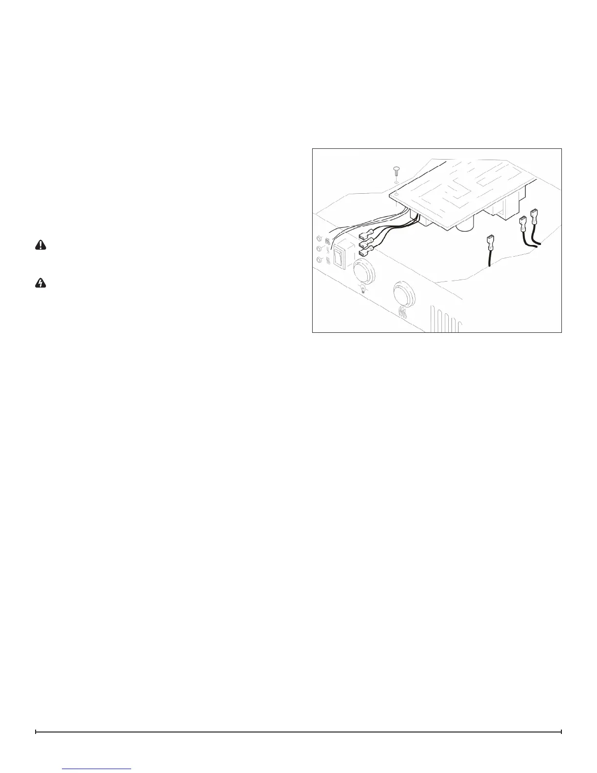
Locate the remote control receiver, mounted on the top 5.
panel, and disconnect the wiring clips and connections,
noting their original locations.
!
NOTE: Using a at head screwdriver gently pry be-
tween the end of the connectors and the remote control
receiver to release the wires.
From under the panel, break off the six mounting studs 6.
on the remote control receiver by grasping with pliers
and twisting on the protruding part of the stud. Push
the remainder of the studs out through the top panel.
Properly orient and mount the new remote control 7.
receiver, using the new mounting studs, provided, and
reconnect all of the wiring connections.
For units with attached LED lights: Pull the red LED 8.
indicator lights out through the back of the top panel,
taking note of the sequence for reinstallation.
!
NOTE: Gently pressing on the front of the LED with a
at head screwdriver will assist in removing them.
Install the new LED indicator lights.9.
Locate the 3-Position Switch mounted on the top panel 10.
and disconnect the wiring clips and connections noting
their original locations. (If required.)
!
NOTE: Using a at head screwdriver, gently pry be-
tween the end of the connectors and the remote control
receiver to release the wires.
Depress the retainer clips on the rear of the 3-Position 11.
Switch and push the switch out of the front of the top
panel.
Properly orient the new 3-Position Switch and recon-12.
nect all of the wires and connections.
Reassemble in the reverse order.13.
Figure 17