13
Depress the retainer clips on the rear of the switch and 6.
push the switch out of the rear cover.
Properly orient the new switch and connect all of the 7.
wiring clips and connections.
Reassemble in the reverse order.8.
HEATER ASSEMBLY REPLACEMENT
Tools Required: Phillips head Screwdriver
Flat Head Screwdriver
CAUTION: If the replace was operating prior to ser-
vicing allow at least 5 minutes for light bulbs and heating
element to cool off to avoid accidental burning of skin.
WARNING: Disconnect power before attempting any
maintenance or cleaning to reduce the risk of electric
shock or damage to persons.
Remove the rebox trim by inserting a slotted screw-1.
driver and turning ¼ of a turn to release the trim from
the rebox.
Remove the rebox from the mantel.2.
Lower the grille covering the controls.3.
Remove the retaining screws on the top cover and 4.
remove the top, being careful not to damage any of the
wiring.
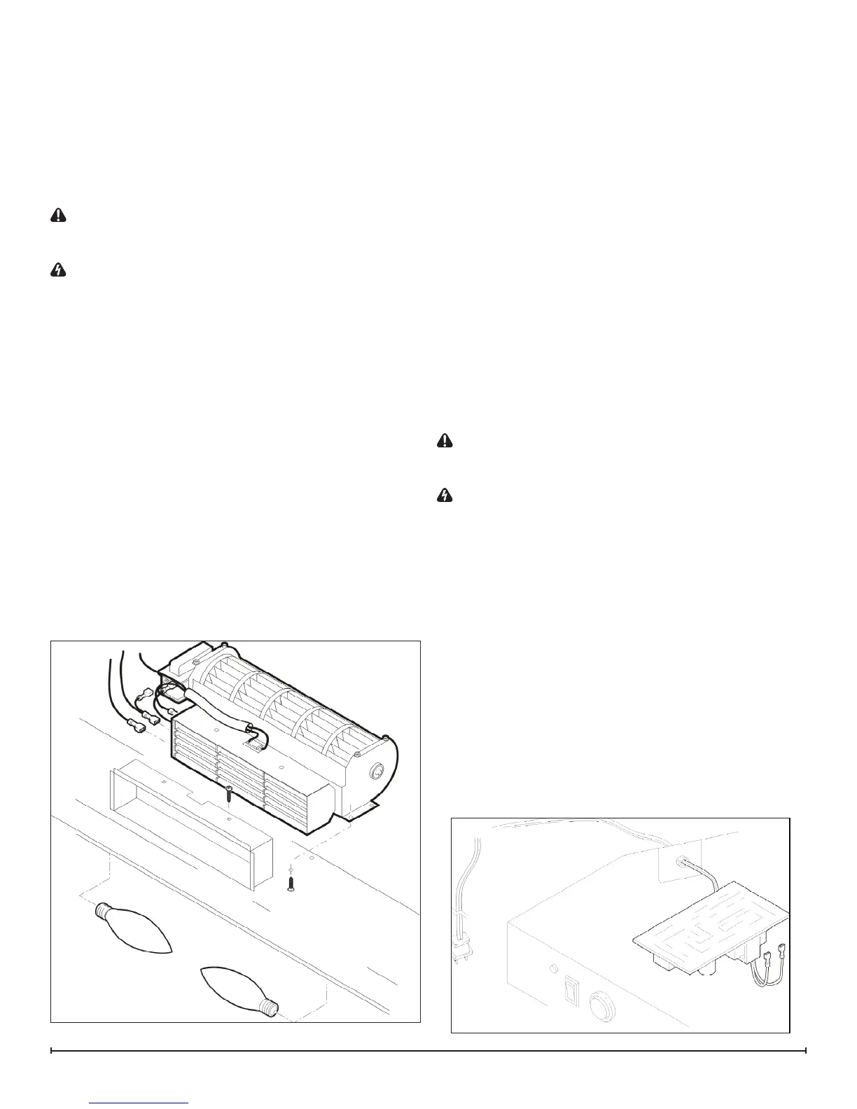
Locate the heater assembly and disconnect the wiring 5.
clips and connections, noting their original locations.
Remove the mounting screw in the center of the glass 6.
and remove the retainer bracket.
Remove the glass by lifting up from the bottom. Set 7.
the front glass aside, in a safe place.
Locate the two upper bulbs inside the rebox at the top.8.
Hold the light sockets while unscrewing the bulbs.9.
Remove the yellow wire from the heater element, com-10.
ing from the heater on/off switch.
Remove the blue wire from the remote control receiver 11.
coming from the temperature cutoff switch.
Remove the 2 element mounting screws from the top 12.
of the element located on both sides of the temperature
cutoff switch. (Figure 15)
Remove the 4 heater assembly mounting screws from 13.
inside the rebox and set aside the heater assembly.
Disconnect wiring connections and connect to replace-14.
ment heater assembly, noting their original locations.
!
NOTE: Using a at head screwdriver gently pry be-
tween the end of the connectors and the heater to release
the wires.
Properly orient the new heater assembly and connect 15.
any remaining wiring connections.
Reassemble in the reverse order as above.16.
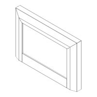
POWER CORD REPLACEMENT
Tools Required: Phillips head Screwdriver
Flat Head Screwdriver
CAUTION: If the replace was operating prior to ser-
vicing allow at least 5 minutes for light bulbs and heating
element to cool off to avoid accidental burning of skin.
WARNING: Disconnect power before attempting any
maintenance or cleaning to reduce the risk of electric
shock or damage to persons.
Remove the rebox trim by inserting a slotted screw-1.
driver and turning ¼ of a turn to release the trim from
the rebox.
Remove the rebox from the mantel.2.
Lower the grille covering the controls.3.
Remove the retaining screws on the top cover and 4.
remove the top, being careful not to damage any of the
wiring.
Locate and disconnect the power cord wiring con-5.
nections, noting their original locations on the remote
control receiver.
!
NOTE: Using a at head screwdriver gently pry be-
tween the end of the connectors and the remote control
receiver to release the wires.
Figure 15
Figure 16