14 www.dimplex.com
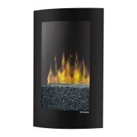
Main Power
3 Position Switch
Dimmer Control Board
“P” - Connects to the Terminal Block
“P1” - Connects to the
Potentiometer
“L” - Connects to Upper Lights
“P2” - Connects to the
Potentiometer
Terminal Block
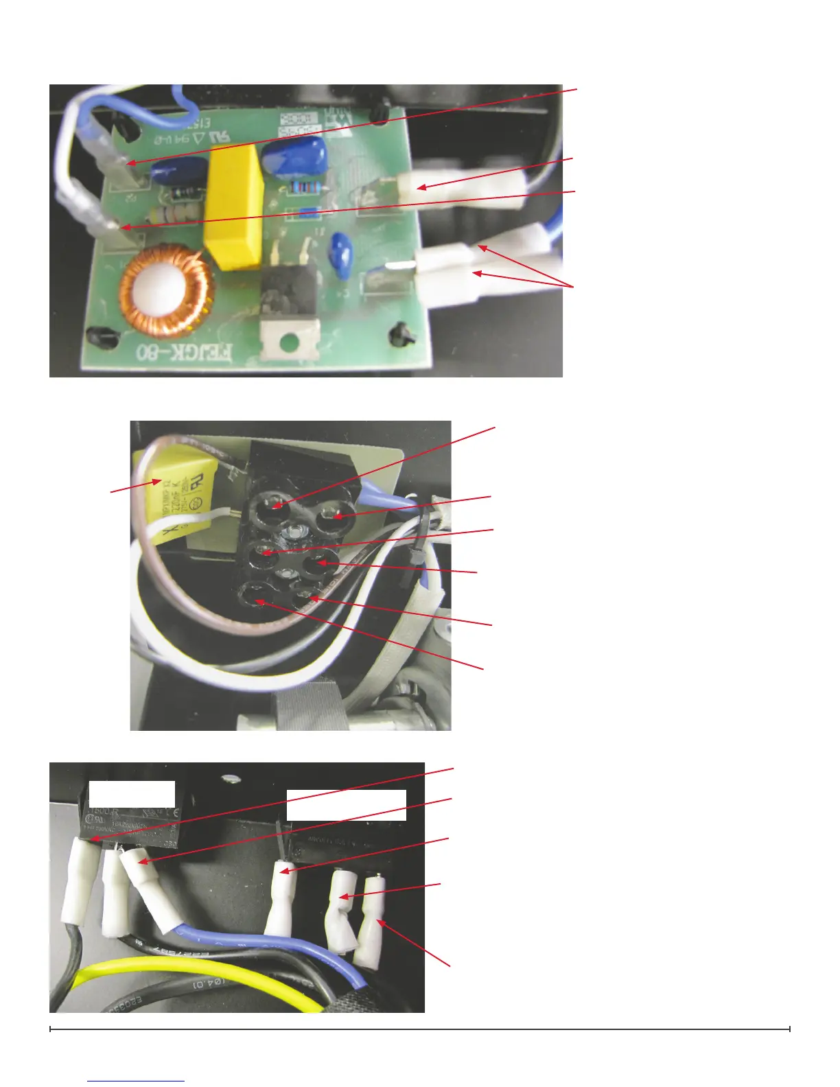
Capacitor
Connects to the Lower Light Assembly and the
Remote Control Receiver Board
Connects to Capacitor and Flicker Motor
Connects to the “On” side of the Heater Switch
and the Lower Light Assembly
Connects to Capacitor and Flicker Motor
Connects to Flicker Motor
Empty
Switch Housing Interior View
Connects to the Terminal Block and the High
Temperature Cutout
Connects to Switch Output on Remote Control
Receiver Board
Connects to the “L” on the Remote Control
Receiver Board
Connects to Thermostat
Power Cord
Heater On/Off
Switch
 Loading...