DNDS Modular
DNDS Modular DNDS Modular
DNDS Modular
O
OO
Original
riginal riginal
riginal Betriebsanleitung
BetriebsanleitungBetriebsanleitung
Betriebsanleitung
Original Instruction Manual
Original Instruction Manual Original Instruction Manual
Original Instruction Manual
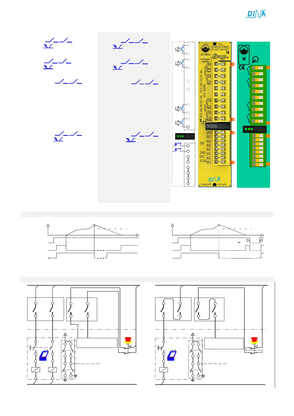
DNDS PMG and DNDS OM, PM: Output module
Für Stillstandsüberwachung
2 Kontakte
13 14 23
24
und
1 Ausgang
OS
positivschaltend
Für Drehzahlüberwachung
2 Kontakte
33 34 43
44
und
1 Ausgang
OD
positivschaltend.
STOP Kontakte
• Die Kontakte
13 14 23
24
sind
offen bei Bewegung und
geschlossen im Stillstand.
• Diese können zur Verriegelung
einer Schutzeinrichtung im Auto-
matikbetrieb eingesetzt werden.
• Bei Bewegung sperrt Ausgang SO,
LED links ist dunkel.
SPEED Kontakte
• Die Kontakte
33 34 43
44
und
der Ausgang
OD
Schalten ab
bei V>Vmax.
• Diese sind aktiv bei V<Vmax.
• Vmax wird über die F- bzw.
D-, R1- und SH-Klemme gewählt.
• LED rechts ist dunkel bei V>Vmax
und grün bei V<Vmax.
• Siehe auch Wiedereinschaltsperre.
• LED links und rechts sind dunkel
bei fehlendem Messsystem.
• Diese blinken (kurz grün, lang
dunkel)bei einem internen Fehler.
For standstill monitoring
2 contacts
13 14 23
24
and an
output
OS
positively switching
For speed monitoring
2 contacts
33 34 43
44
and an
output
OD
positively switching
STOP contacts
• The contacts
13 14 23
24
are
open in motion and close during
Standstill.
• These contacts can be used to
interlock the safe cover during
the automatic function mode.
• The output SO is off and LED left
is dark in motion.
SPEED contacts
• The contacts
33 34 43
44
and
the output
OD
switch off if
V>Vmax.
• These are active if V<Vmax.
• Vmax is to select via F- or rather
D-terminals, R1- and SH-terminal.
• LED right is dark if V>Vmax and
green if V<Vmax.
• See also restart interlock.
• LED left and right are dark with-
out measuring system.
• These are flashing (short green,
PM / PMG
0V
STOP
SPEED
UB
24
23
14
13
SPEED
STOP
A1
33
34
43
44
A2
24V
DC
NC
NC
STOP
SPEED
P.D. B300
STOP
SPEED
DO
SO
A2
A2
A1
A1
A1
A1
44
43
34
33
24
23
14
13
DC1: 6A DC13: 4A
AC1: 6A AC15: 3A
US LISTED
IND.CONT.EQ
R
L
U
1ZD7
DNDS PM
B
G
-
P
R
U
F
Z
E
R
T
ET 13012
Sicherheit geprüft
tested safety
ID-No:10PM00
A1
24V
DC
0.5A
A2
0V
0.1A
DNDS MODULAR OUTPUT MODULE
DINA ELEKTRONIK
D-72649 WOLFSCHLUGEN
ON
SPEED
STOP
UB
13-14, 23-24
33-34, 43-44
V
V>Vmax.
t
UB
13-14, 23-24
33-34, 43-44
V
V>Vmax.
t
>2s
Paralleler Anschluss der Ausgänge
Serieller Anschluss der Ausgänge
Parallel connection of the outputs
Serial connection of the outputs
NOT-HALT Kreis
44
43
34
33
13
14
23
24
STOP
SPEED1
L1
L2
Tür
DNDS
DNDS
Quit
Schutztürschalter
11
13
12
14
21 23
22
24
24V DC
CNC
Emergency stop circuit
Protection cover switch
Cover
entriegeln
unlock
44
43
34
33
13
14
23
24
STOP
SPEED1
L1
L2
DNDS
11
13
12
14
21 23
22
24
24V DC
CNC
NOT-HALT Kreis
Emergency stop circuit
Tür
entriegeln
Cover unlock
Schutztürschalter
Protection cover switch
Quit
DNDS
 Loading...
