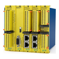
DNDS Modular
DNDS Modular DNDS Modular
DNDS Modular
O
OO
Original
riginal riginal
riginal Betriebsanleitung
BetriebsanleitungBetriebsanleitung
Betriebsanleitung
Original Instruction Manual
Original Instruction Manual Original Instruction Manual
Original Instruction Manual
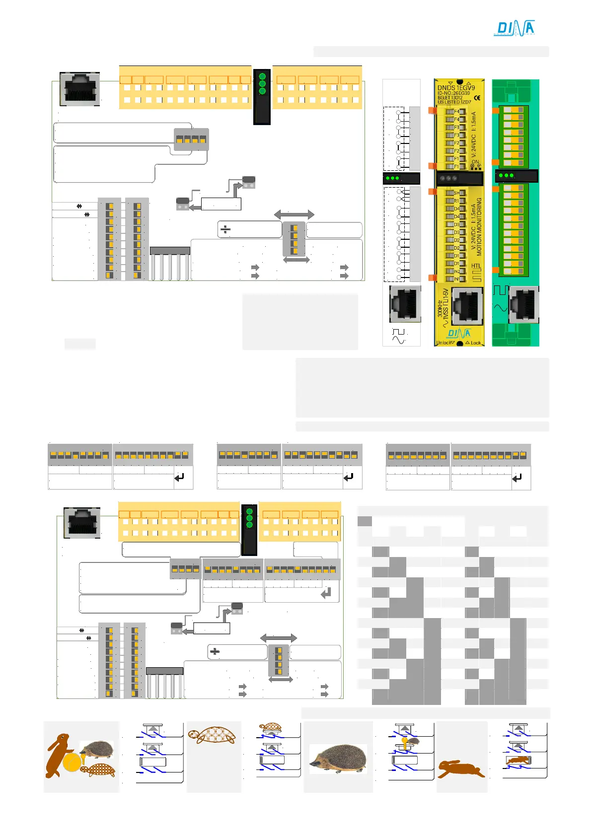
G/ 1E V6, V9/ Inkrementelles System
S4
on: Wiedereinschaltsperre (WES)
Restart: UB 2s unterbrechen
on: restart interlock (WES)
restart pwr 2s disconnected
on:Messsystemspannung aus DNDS
on:Measuring system pwr from DNDS
Messsystem
Measuring system
F1 F2 F3 F4IN1IN2 D1 D2 D3 D4 SH R1
on
9
8
7
6
5
4
3
2
1
10
on
9
8
7
6
5
4
3
2
1
10
S1
S2
Filter 25 50Hz
Divisor x4 x2
1
2
4
8
16
32
64
128
Einstellung
adjustment
Teiler
Divisor
S3
Teiler variabel
divisor variable
on
1 2 3 4
Teiler konstant
divisor constant
Jumper
Überwachung/ monitoring
Sin +Cos
2 2
240Hz 600Hz
SH R1
50Hz 125Hz
SH R1
SH 24V/
Tool setting mode:
R1 24V
Semi-automatic:
Einrichtbetrieb:
Halbautomatik:
SH 24V/ R1 24V
STOP
ON
SPEED
V6
96Hz 600Hz 50Hz 125Hz
V6 26EE09
on
1234
1EG V9
1EG V9 1EG V9
1EG V9
1E V6, V9
1E V6, V91E V6, V9
1E V6, V9
IN2
IN1
D1
D2
D3
D4
SH
R1
F1
F2
F3
F4
1-5V
1Vss
300KHz
1V
PP
SPEED
UB
STOP
1E
1EG
V6
V7
V9
F3
F2
F2
F1
F1
F3
F4
F4
IN1
IN2
D1
D1
D2
D2
D3
D3
D4
D4
R1
SH
1-5V
1VSS
1Vpp
300KHz
SPEED
STOP
ON
DIP Schalter nur bei V9
• S6 Position 1-8: Interne Konfiguration der D-Klemmen.
• S7 Position 1-8: Interne Konfiguration der F-Klemmen
• S7 Position 9+10: on Konfiguration extern über F-Klemmen
• Off Konfiguration intern über Position 1-8
•
Bei intern wird nur die F4 Klemme angesteuert
DIP switches V9 only
• S6 position 1-8: Internal configuration of the D-Terminals.
• S7 position 1-8: Internal configuration of the F-Terminals
• S7 position 9 + 10: on configuration external via F-Terminals
• Off configuration internal via position 1-8
•
Termial must be controlled.
Beispiele interne
Beispiele interne Beispiele interne
Beispiele interne
Konfiguration an V9
Konfiguration an V9Konfiguration an V9
Konfiguration an V9
Klemmen
KlemmenKlemmen
Klemmen
Example internal configuration on V9
Example internal configuration on V9Example internal configuration on V9
Example internal configuration on V9
Terminals
TerminalsTerminals
Terminals
F1
F2F3F4
F1
F2F3F4
off
D1D2D3D4 D1D2D3D4
D Auswahl intern
S6: D1-D4 intern 500Hz
S7: F1-F4 extern
D selection internal
F Auswahl intern
F selection internal
on
1 2 3 4 5 6 7 8
on
1 2 3 4 5 6 7 8 9 10
F1
F2F3F4
F1
F2F3F4
off
D1D2D3D4 D1D2D3D4
D Auswahl intern
S6: D1-D4 intern 500Hz
S7: F1-F4 intern 75%
D selection internal
F Auswahl intern
F selection internal
on
1 2 3 4 5 6 7 8
on
1 2 3 4 5 6 7 8 9 10
F1
F2F3F4
F1
F2F3F4
off
D1D2D3D4 D1D2D3D4
D Auswahl intern
S6: D1-D4 extern
S7: F1-F4 extern
D selection internal
F Auswahl intern
F selection internal
on
1 2 3 4 5 6 7 8
on
1 2 3 4 5 6 7 8 9 10
S 4
on
1 2 3 4
on: Wiedereinschaltsperre
Restart: UB 2s aus
on: restart interlock
restart pwr 2s off
on:Messsystemspannung aus DNDS
on:Measuring system pwr from DNDS
on
1 2 3 4 5 6 7 8 9 10
F1
F2F3F4
F1
F2F3F4
off
on
1 2 3 4 5 6 7 8
D1D2D3D4 D1D2
D3 D4
D Auswahl intern
S6 S7
D selection internal
F Auswahl intern
F selection interna
l
9/10 on: F1-F4
extern/external
Messsystem
Measuring system
F1 F2 F3 F4IN1IN2 D1 D2 D3 D4 SH R1
on
9
8
7
6
5
4
3
2
1
10
on
9
8
7
6
5
4
3
2
1
10
S1
S2
Filter 25 50Hz
Divisor x4 x2
1
2
4
8
16
32
64
128
Einstellung
adjustment
Teiler
Divisor
S3
Teiler variabel
divisor variable
on
1 2 3 4
Teiler konstant
divisor constant
240Hz 600Hz
SH
R1
50Hz 125Hz
SH R1
SH 24V/
Tool setting mode:
R1 24V
Semi-automatic:
Einrichtbetrieb:
Halbautomatik:
SH 24V/ R1 24V
STOP
ON
SPEED
V9
Bei dem frühren Module ist S4 zwischen S6 und S7
At the previous module S4 is between S6 and S7
Jumper
Überwachung/ monitoring
Sin +Cos
2 2
►
►
15
1250
100
Standstill
24V
SH
R1
Fx
Dx
Einrichten
Tool setting
24V
SH
R1
Fx
Halbautomatik
Semi-automatic
24V
SH
R1
Fx
Dx
Automatik
Automatic
24V
SH
R1
Fx
 Loading...