DNDS Modular
DNDS Modular DNDS Modular
DNDS Modular
O
OO
Original
riginal riginal
riginal Betriebsanleitung
BetriebsanleitungBetriebsanleitung
Betriebsanleitung
Original Instruction Manual
Original Instruction Manual Original Instruction Manual
Original Instruction Manual
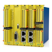
1PMG - 8PMG 1 - 8 1EG +1RG PMG
13 14 23
24
OS
33 34 43
44
OD
1M – 8M
1PM - 8PM
1 - 8 1E + 1R
OM
PM
13 14 23
24
OS
33 34 43
44
OD
1VMG - 8VMG 1 - 8 1EG + 1RG VMG
13 14 23
24
33 34 43
44
57 58 67
68
1VM - 8VM 1 - 8 1E + 1R VM
13 14 23
24
33 34 43
44
57 58 67
68
2GMG - 8GMG 2 - 8 1EG + 1RG GMG
13 14 23
24
33 34 43
44
53 54 63
64
2GM - 8GM 2 - 8 1E + 1R GM
13 14 23
24
33 34 43
44
53 54 63
64
1GMG - 8GMG V1
1 - 8 1EG + 1RG GMG V1
13 14 23
24
33 34 43
44
57 58 67
68
1GM - 8GM V1 1 - 8 1E + 1R GM V1
13 14 23
24
33 34 43
44
57 58 67
68
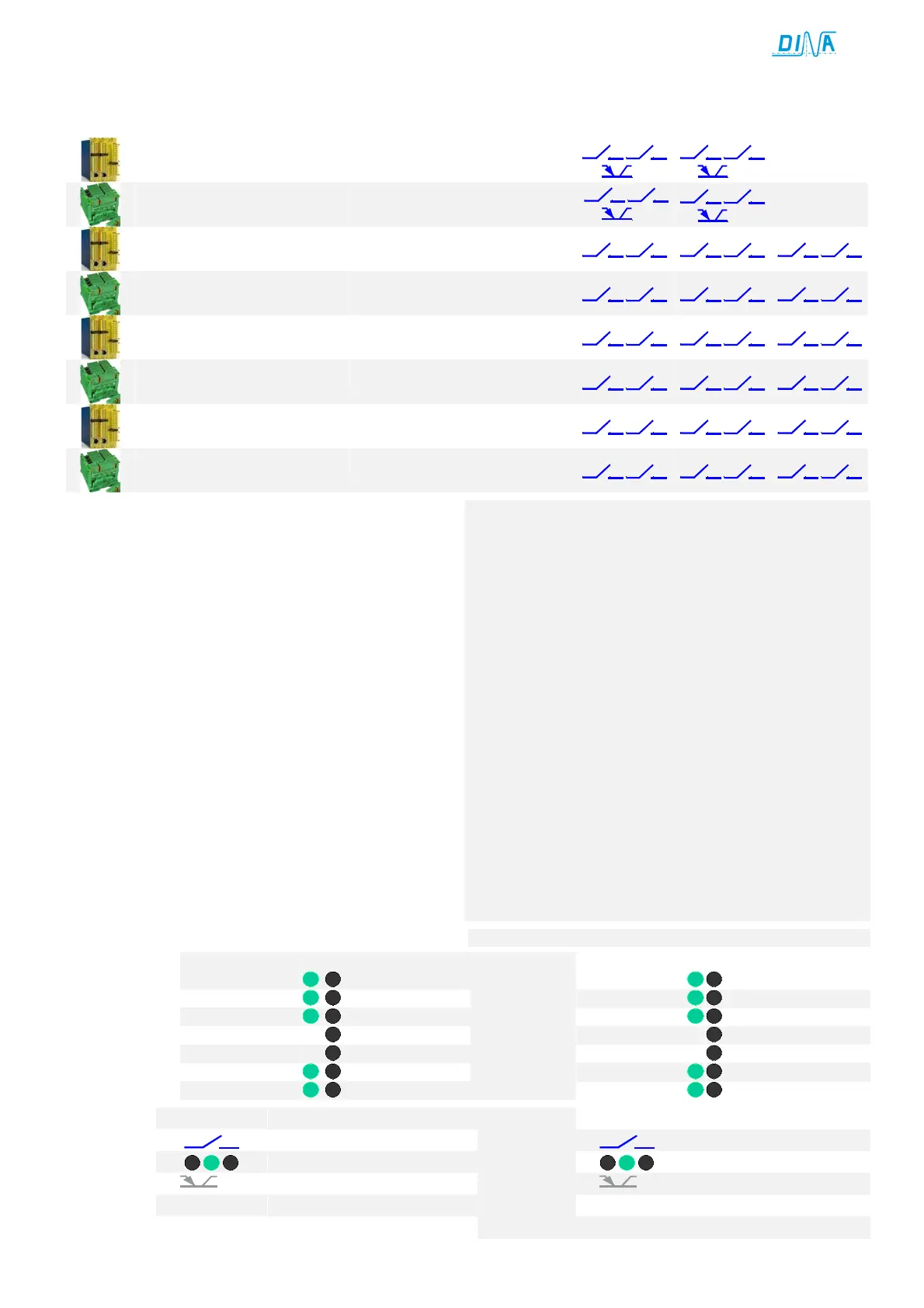
• IN1, IN2 für 2 PNP Sensoren als Messsystem.
• Anschluss IN2 an 24V, IN1 offen: unterdrückt Modulfunktion
nur für besondere Fälle vorgesehen.
• D-Klemmen an 1E V6, V7, V9 / 1R V1 / 1EG V9 / 1RG V1
Auswahl der Drehzahl im Automatik betrieb
nur aktive bei mindestens eine F-Klemme an 24V
• F-Klemmen: Reduzierung der Auswahl an D-Klemmen
100-25%
Umschalter zwischen automatikbetrieb (Fx an 24V und
Einrichtbetrieb (F offen)
• R1-Klemme: zur Auswahl des Halbautomatikbetriebs
R1-Klemme ist nur aktiv, wenn alle F-klemmen offen sind.
• SH-Klemme: zur Auswahl der des Einrichtbetriebs
SH ist nur aktiv, wenn R1- und F-Klemmen offen sind.
• D-Klemmen an 1E, 1EG V7A, V7C / 1R, 1RG V2, V3C
Auswahl der Drehzahl im Automatikbetrieb
Umschalter zwischen automatikbetrieb (Dx an 24V und
Einrichtbetrieb (D offen)
• M-/ MT-Klemmen: Unterdrückung der Modulfunktion
nur in besonderen Fällen an 24V anschließen.
• R1-Klemme: zur Auswahl des Halbautomatikbetriebs
R1 ist nur aktiv, wenn D-, M- bzw. MT-klemmen offen sind.
• SH-Klemme: zur Auswahl der des Einrichtbetriebs
SH ist nur aktiv, wenn D-, M- bzw. MT-klemmen offen sind.
• Alle Klemmen sind 10ms einschalt- und 1s
Function of the terminals
• IN1, IN2 for 2 PNP sensors as measuring system.
• Connection IN2 to 24V, IN1 open: muting the module function
only to use if necessary.
• D-Terminals at 1E V6, V7, V9 / 1R V1 / 1EG V9 / 1RG V1
setting of the speed during the automatic function mode
active only if at least one F-terminal is connected to 24V.
• F-Terminals: reduction of the selection at D-Terminals
100-25%
switch over between automatic mode (Fx connected to 24V
and tool-setting function mode (F = NC)
• R1-Terminal: to select the semi-automatic mode
R1-Terminal is only active if the F-Terminals are off.
• SH-Terminal: to select the tool setting mode
SH-Terminal is only active, if R1- and F-Terminals are NC.
• D-Terminals at 1E, 1EG V7A, V7C / 1R, 1RG V2, V3C
selection of the speed during the automatic function mode
switch over between automatic mode (Dx connected to 24V
and tool-setting function mode (D = NC)
• M-/ MT-Terminals: muting of the module function
only to connect to 24V if necessary
• R1-Terminal: to select the semi-automatic mode
R1 is only active if the D-, M- respectively MT-Terminals are off.
• SH-Terminal: to select the tool setting mode
SH is only active, if D-, M- respectively MT-Terminals are off.
• All terminals are10ms switch on and 1s switch off delayed.
Störungen
on failure
Adjustment of input modules
 Loading...