4.4. ADJUSTMENT OF OUTREACH- AND OVERLOAD LIMIT SWITCHES
While adjusting the limit switches, use
the same test loads as in testing the limit
switches.
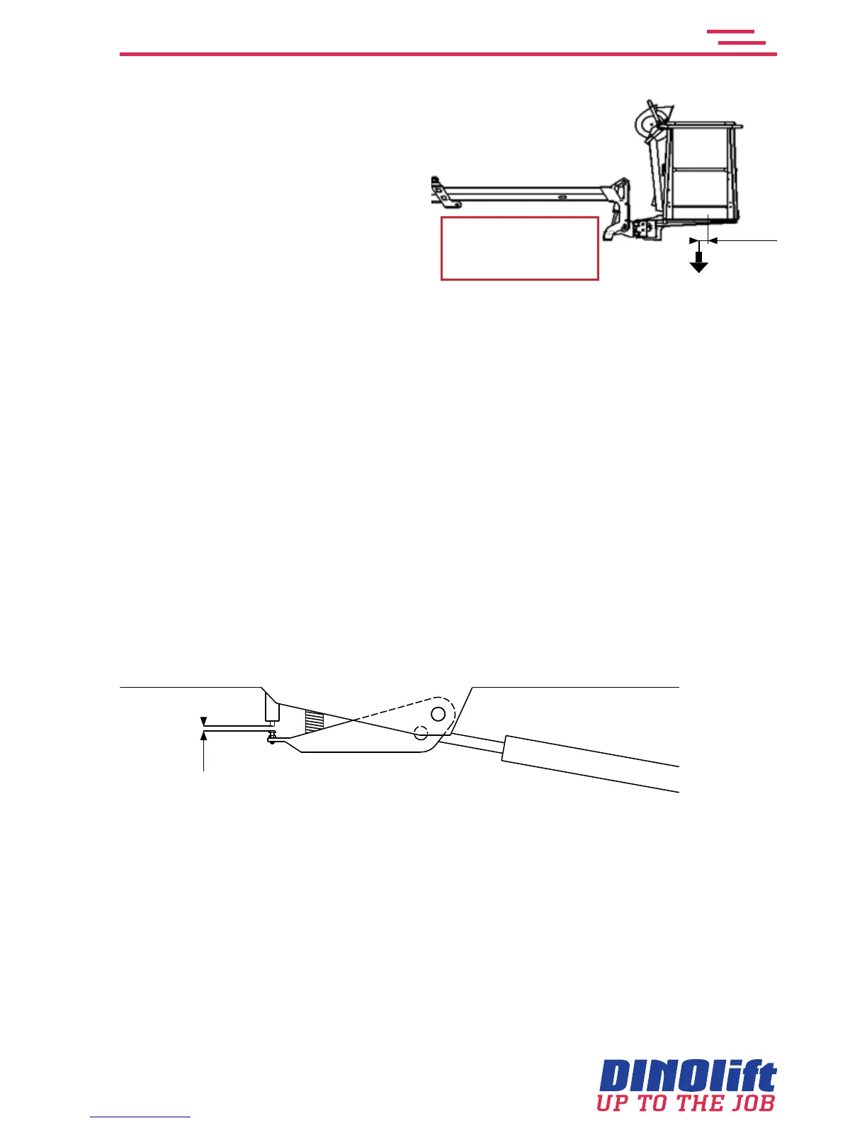
The adjustment of the limit switches
may only be carried out after the raising
of the platform´s rear edge
To adjust overload limit switch RK5
1. Remove the cover
2. Adjust the RK4 to make sure that the RK5 with certainty trips before it
3. extendthetelescopeandmeasurethestroke(L)
4. Thelengthshallbe: 205RXT:L=1600mm+0mm/-50mm
240RXT:L=2100mm+0mm/-50mm
265RXT:L=1900mm+0mm/-50mm
5. Tighten the locking nut for adjustment of RK5
6. Check once more the set values of the RK5. Check that the red signal light on the
platformwillashandthefollowingtextisdisplayed: Atthelimitforsafeoperation!
To adjust overload limit switch RK4
7. Adjust the RK4 to closer than the RK5
8. Retractthetelescopeandthenextenditagain(inhorisontalposition)
9. Measurethestroke(L)
The length should be: 205RXT: L = 1350 mm +0/-50mm
240RXT: L = 1800 mm +0/-50mm
265RXT: L = 1600 mm +0/-50mm
10. Tighten the locking nut for adjustment of RK4 and check the values once more.
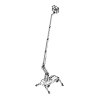
ThegapbetweentheadjustmentscrewandthetipofthelimitswitchRK4shallbe1-3mm
RK4
1-3mm
11. Apply a safety wire to the adjustment screws in such a way that it will be impossible to
turn the screws outwards from the limit switches.
12. Apply a seal on the wire
13. Put the cover back in its place
205RXT: w = 215 kg
240RXT: w = 80 kg
265RXT: w = 80 kg
100 mm
w