Do you have a question about the Dinolift 240RXT and is the answer not in the manual?
Formal statement confirming compliance with EU directives and harmonized standards.
Illustration and explanation of the machine's identification plate details.
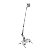
Overview of the machine's essential parts and concepts.
Defines the authorized applications and limitations for the access platform.
Critical guidelines for safe use of the lift, including load limits and environmental conditions.
Details the function of safety limit switch RK3 for outrigger and driving device operation.
Specifies outrigger deployment requirements before lifting the boom and associated limit switches.
Explains limit switches RK4 and RK5 for preventing overloading and exceeding outreach limits.
Describes the function of the emergency stop button and its reset procedure.
Identifies and explains the functions of controls on the chassis-mounted control panel.
Identifies and explains the functions of controls on the platform-mounted control panel.
Procedures to follow when the lift's stability is compromised due to faults or external forces.
Steps to take when the lift is overloaded to restore safe operation.
Procedure for lowering the boom using the emergency descent system when power fails.
Steps to take if the emergency descent system itself malfunctions or is unavailable.
Ensures the ground is stable and suitable for operating the lift, with load pressure guidelines.
Step-by-step guide for starting both the combustion and electric engines.
Instructions for safely shutting down the combustion and electric engines.
How to adjust and select driving speed using control levers and switches.
Options for selecting 2-wheel, 4-wheel, or crab steering modes.
Procedures for driving the machine with the boom in a raised position.
Detailed steps for operating the lift using the combustion engine and its components.
How to deploy and level the support outriggers for stable operation.
Operation and verification of the optional automatic levelling system.
Procedures for operating the lift from the platform control panel.
Procedures for operating the lift from the chassis control panel.
Details the battery, hydraulic unit, and motor specifications for the emergency descent system.
Steps for retracting the boom and lowering the articulated arm using the emergency system.
Procedure for using the emergency system to raise support outriggers to the transport position.
Guidelines for performing servicing and maintenance tasks on the lift.
Procedures for daily, weekly, bi-annual, and annual servicing and inspections.
Details the tasks and intervals for routine maintenance, including oil changes and filter replacements.
Specifies lubrication points and frequency for various components of the lift.
Procedures for checking and servicing valves that control load holding and regulation.
Explains the slave cylinder system and troubleshooting for platform levelling.
Initial inspection and test loading performed by the manufacturer.
Template for recording inspection results and findings.
Essential checks performed by the user at the start of each workday or at a new site.
Detailed inspection tasks to be performed monthly by a qualified person.
Comprehensive inspection required annually, focusing on structural integrity and safety systems.
Inspection required after the lift has sustained damage or been in an unusual situation.
Procedures for performing test loadings to verify structural integrity and stability.
Troubleshooting steps for common issues preventing the engine from starting.
Diagnosing and resolving problems when the engine starts but then stops.
Troubleshooting when platform movements fail while driving is operational.
Identifying causes for the outriggers not deploying or retracting.
Resolving issues where driving functions are unavailable with outriggers in transport position.
Addressing irregular or partial movement malfunctions of the platform.
Diagnosing and fixing issues where the boom slowly lowers on its own.
Troubleshooting steps when the boom fails to lift.
Resolving issues where the telescope extension or retraction fails.
Identifying causes for slow retraction of the telescope.
Troubleshooting leaks in load regulation valves causing platform drift.
Addressing issues where outriggers fail to maintain their support or transport position.
Troubleshooting problems with the driving device, particularly brake dragging.
Explanation of relays and functions within the main control centre (PK).
Description of buttons, switches, and signal lights on control centre 2 (OK2).
Details of displays, joysticks, and switches on control centre 1 (OK1).
Explanation of various limit switches (RK3-RK18) and their functions in controlling machine movements.
Description of relays and buttons associated with outrigger and levelling controls in the chassis centre.
Glossary of component abbreviations and their meanings.
Table listing electrical components with reference numbers, part numbers, and descriptions.
| Brand | Dinolift |
|---|---|
| Model | 240RXT |
| Category | Boom Lifts |
| Language | English |