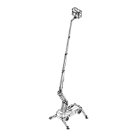
DINO 240RXT
79
20.5 CHASSIS CONTROL CENTRE (AK)
F7: Outriggers, feed to XP-A1- module (10 A).
F14: Outriggers, feed to XP-A1- module (10 A).
K30: Control relay. Control relay for the outrigger 1, upwards.
K31: Control relay. Control relay for the outrigger 1, downwards.
K32: Control relay. Control relay for the outrigger 2, upwards.
K33: Control relay. Control relay for the outrigger 2, downwards.
K34: Control relay. Control relay for the outrigger 3, upwards.
K35: Control relay. Control relay for the outrigger 3, downwards.
K36: Control relay. Control relay for the outrigger 4, upwards.
K37: Control relay. Control relay for the outrigger 4, downwards.
K38: Control relay. Release of the brakes on the drive motors, operates during the execution of the
driving or turning movements.
K39: Control relay. Control of the outrigger selector valve, is active during the operation of the
outriggers.
K43: Control relay for automatic levelling. Sets off the automatic levelling.
K44: Control relay for automatic levelling. Sets off the simultaneous lifting of the outriggers.
S32: Emergency descent button. Starts the emergency descent unit for operation of support outriggers
(the mains current of the lift must be switched on).
XP-A1: Power supply unit.
Bus module used for controlling the propo valves and relays and as a connection terminal for the
sensors.