DINO 240RXT
21
Lx-A0 Lx-A1
9.2 CONTROLS ON THE PLATFORM PANEL OK1
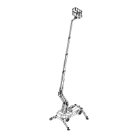
LX-A0 Control lever (left joystick)
LX-A1 Control lever (right joystick)
AD Level display of chassis
F13 Platform swing fuse
Q1 Switch lock, positions:
0 - ignition off
1 - power on, operating position
2 - glowing
3 - start
H1 Red signal light, alarm
H4 Green signal light, support outrigger limit-switches
H5 Orange signal light, glowing
MDM Display/adjustment device
PR Socket outlet 230VAC/ 10A (2 pcs)
S4 Emergency stop
- push to stop
- pull to reset
S11 Emergency descent device start button
S12 Sound signal
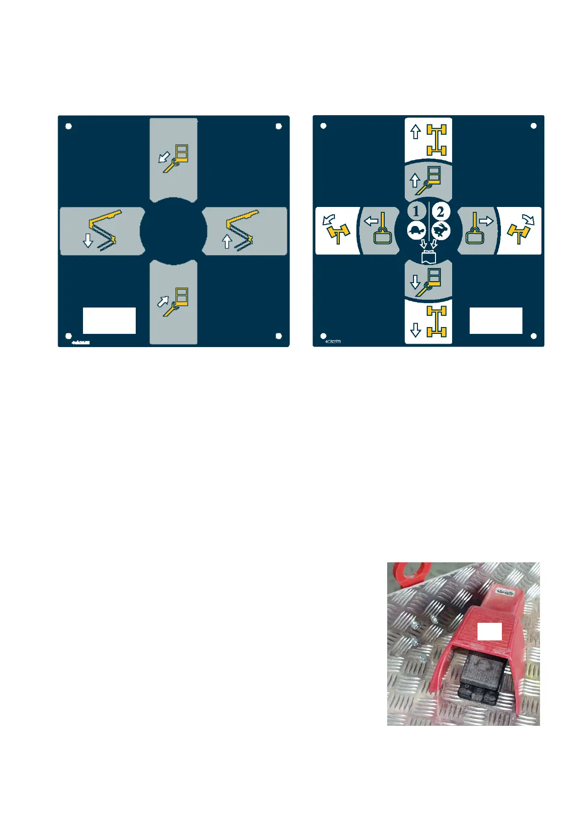
S21 Support outrigger 1 control
S22 Support outrigger 2 control
S23 Support outrigger 3 control
S24 Support outrigger 4 control
S25 Platform levelling lever switch
S26 Driving with raised boom, by-pass of support outriggers
S27 Selection of steering mode, positions:
1 = 2-wheel steering
2 = 4-wheel steering
3 = crab- steering
S28 Pedal. Operates as Dead-man-switch.
When pushed down the platform control panel remains
operational
S29 Turning the platform
S31 Telescope in, pushbutton
S28
 Loading...